A mining imaging device, equipment and method

An imaging device and imaging module technology, which is applied in image communication, TV, color TV parts, etc., can solve the problem that visible light cameras and visible light supplementary lights cannot satisfy the clear imaging of real scenes in mines, and reduce the risk of accidents Probability, increased shooting distance, and improved quality effects

Active Publication Date: 2022-05-03
ANHUI HUIZHOU GEOLOGY SECURITY INST
View PDF9 Cites 0 Cited by
  • Summary
  • Abstract
  • Description
  • Claims
  • Application Information

AI Technical Summary

Problems solved by technology

[0007] The technical problem to be solved by the present invention is: how to solve the problem that the underground imaging equipment adopts the visible light camera and the visible light supplementary light, which cannot satisfy the clear imaging of the real scene in the mine

Method used


Image

  • A mining imaging device, equipment and method
  • A mining imaging device, equipment and method
  • A mining imaging device, equipment and method

Examples


Embodiment 1

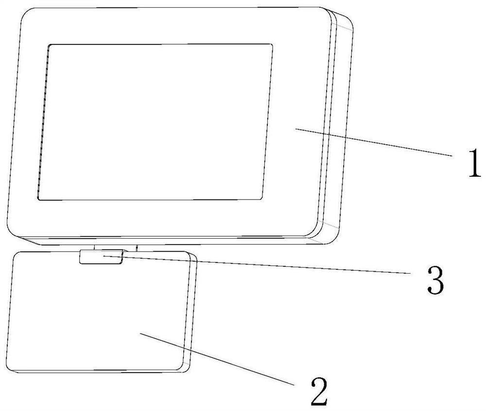
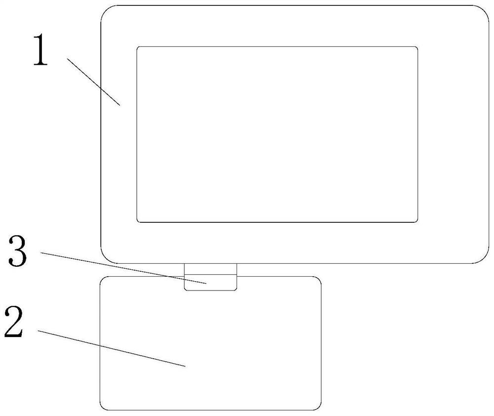
[0054] like figure 1 As shown, a mining imaging device includes an imaging module 1 and a supplementary light 2 for providing infrared light and visible light to the imaging module 1;

[0055] In this embodiment, the supplementary light 2 is installed on the imaging module 1 through the bracket 3; without the bracket 3, the supplementary light 2 can also be held directly or fixed in other ways.

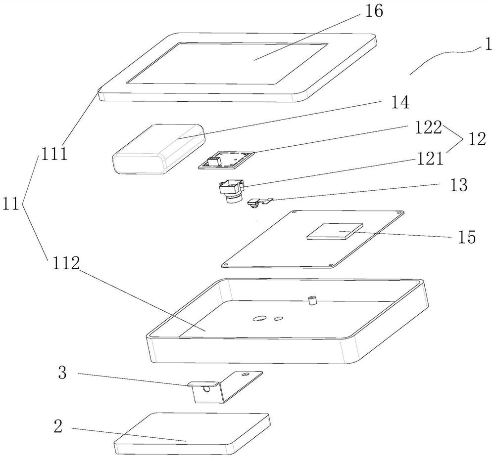
[0056] like figure 2 As shown, the imaging module 1 includes a housing 11 with a cavity, a characteristic spectrum camera 12, a zoom camera 13, a power supply 14, a processor 15, and a display screen 16; the zoom camera in this embodiment is a high-definition zoom camera 13, and the characteristic spectrum The camera 12 and the high-definition zoom camera 13 are all installed on one side of the housing 11, the display screen 16 is installed on the other side of the housing 11, the processor 15 and the power supply 14 are installed inside the housing 11, and the characteristic spectr...

Embodiment 2

[0071] like figure 2 , Figure 5 As shown, the difference between this embodiment and Embodiment 1 is that the bracket 3 is a Z-shaped bracket, the bracket 3 has a connection hole, the fill light 2 is connected to one end of the bracket 3 through bolts or screws, and the imaging The module 1 is connected to the other end of the bracket 3 through bolts or screws.

[0072] In this embodiment, the fill light 2 is installed under the imaging module 1 . Therefore, the detachable connection between the supplementary light 2 and the imaging module 1 is realized, which is convenient for replacement. In addition, other detachable installation methods can be applied here.

Embodiment 3

[0074] An imaging method using the mine imaging device in the first and second embodiments above comprises the following steps:

[0075] S1: Fix the imaging module 1 and the fill light 2 through the bracket 3, turn on the imaging module 1 and the fill light 2 respectively, the processor 15 has a Bluetooth module that can be paired with the fill light 2, and connect the fill light 2 and the imaging module 1 Realize wireless connection;

[0076] S2: The imaging module 1 obtains the optimal fill light parameters, and the imaging module 1 sends the obtained optimal fill light parameters to the fill light 2;

[0077] The specific steps for the imaging module to obtain the optimal fill light parameters include:

[0078] S21: The supplementary light 2 has at least 3 different supplementary light parameters in advance, turn on the light source of the supplementary light, click the pre-shooting button of the imaging module 1 to take pictures of the target object, and the imaging modul...


PUM


Abstract

The invention provides a mining imaging device, which includes an imaging module and a supplementary light; the imaging module includes a housing with a cavity, at least one characteristic spectrum camera, a processor, and a power supply; the characteristic spectrum camera is installed on the housing, and the processor Installed inside the housing, the characteristic spectrum camera is connected to the processor, and the characteristic spectrum camera, fill light, and processor are all electrically connected to the power supply; the characteristic spectrum camera includes a characteristic coated lens and a characteristic spectrum photosensitive CCD, and the characteristic coated lens is located at Characteristic spectrum photosensitive CCD front side. And mine imaging equipment and method using the imaging device. The beneficial effect of the present invention is that image synthesis is performed through setting parameters of the characteristic spectrum camera and the supplementary light, and the problem of poor imaging effect in the imaging process of a specific coal mine is solved.

Description

technical field [0001] The present invention relates to an imaging device and method, in particular to a mining imaging device, equipment and method. Background technique [0002] In coal mine production, it is necessary to record the photos and videos of the scene at the first time. At present, the commonly used imaging equipment in the mine includes video monitoring system, explosion-proof camera, mine imager, mine law enforcement instrument, mine inspection instrument, geological recorder, drilling Peeping instrument etc., above existing equipment all has respective limitation and deficiency when on-the-spot imaging. The main reason is that the shooting is not clear without a special supplementary light device, and the single-camera solution cannot perform clear imaging for special scenes such as head-on and mining areas. Because coal mines contain explosive substances such as gas and dust, all electrical devices underground in coal mines must meet explosion-proof requir...

Claims


Application Information

Patent Timeline
Patent Type & Authority Patents(China)
IPC IPC(8): H04N5/265H04N5/33H04N5/232H04N5/235
CPCH04N5/265H04N5/33H04N23/64H04N23/80H04N23/70
Inventor 陈兴海胡斌谢超张立好王大鹏郭晓梅郭珏刘洪丽
Owner ANHUI HUIZHOU GEOLOGY SECURITY INST
Why Eureka
Try Eureka