
LED packaging method and LED display device

A technology of LED packaging and LED light boards, which is applied in the direction of semiconductor devices, electrical components, circuits, etc., and can solve the problems of cost and product weight increase

Active Publication Date: 2019-08-02
LEDMAN OPTOELECTRONIC HZ CO LTD +1
View PDF3 Cites 0 Cited by
  • Summary
  • Abstract
  • Description
  • Claims
  • Application Information

AI Technical Summary

Problems solved by technology

Since the side light emission of the LED chip cannot pass through the black mask, the cross-light phenomenon is avoided. However, this method increases the mask, resulting in an increase in cost and product weight

Method used


Image

  • LED packaging method and LED display device
  • LED packaging method and LED display device
  • LED packaging method and LED display device

Examples


Embodiment Construction

[0038] The following will clearly and completely describe the technical solutions in the embodiments of the present invention with reference to the accompanying drawings in the embodiments of the present invention. Obviously, the described embodiments are only part of the embodiments of the present invention, not all of them. Based on the embodiments of the present invention, all other embodiments obtained by persons of ordinary skill in the art without creative efforts fall within the protection scope of the present invention.

[0039] It should be noted that all directional indications (such as up, down, left, right, front, back...) in the embodiments of the present invention are only used to explain the relationship between the components in a certain posture (as shown in the accompanying drawings). Relative positional relationship, movement conditions, etc., if the specific posture changes, the directional indication will also change accordingly.

[0040] In addition, in t...


PUM


Abstract

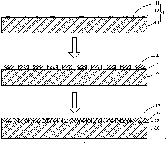
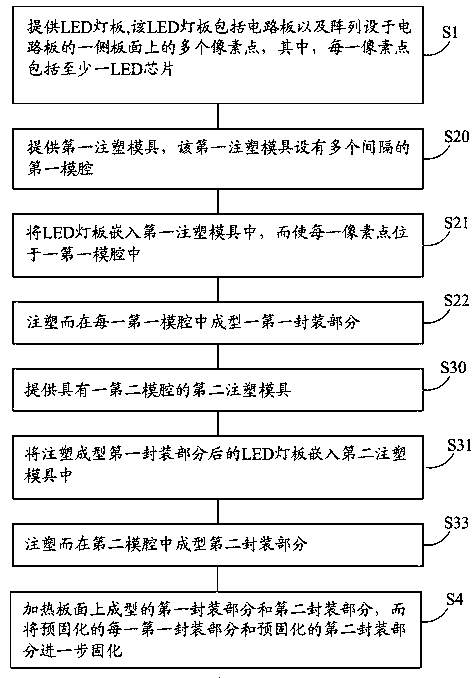
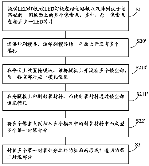
The invention discloses an LED packaging method and an LED display apparatus. The LED packaging method comprises the steps of providing an LED lamp panel, wherein the LED lamp panel comprises a circuit board and multiple pixel points arranged on one side board surface of the circuit board in an array form, wherein each pixel point comprises at least one LED chip; forming multiple first packaging parts for coating the multiple pixel points on the board surface, wherein each pixel point is arranged corresponding to one first packaging part and adjacent two first packaging parts are isolated mutually; and packaging the board surface outside the multiple first packaging parts to form a non-transparent second packaging part. By adoption of the LED packaging method, a mask is not needed, and the problem of optical crosstalk of an LED display screen can be solved.

Description

technical field [0001] The invention relates to the technical field of LEDs, in particular to an LED packaging method and an LED display device. Background technique [0002] With the rapid development of small-pitch LED displays, the pixel pitch is getting smaller and smaller, making the process more and more difficult. The manufacturing process of the existing small-pitch LED display usually includes steps such as die bonding, wire bonding, and packaging of LED chips. Due to the small pixel pitch, crosslight between pixels is prone to occur, which in turn affects the display effect. [0003] In order to solve the problem of cross-lighting, in the prior art, a black mask is firstly installed on the PCB, and the black mask forms a space between adjacent LED chips, and the space is filled with packaging materials to complete the packaging of the LED chips. Since the side light of the LED chip cannot pass through the black mask, the phenomenon of cross-lighting is avoided. Ho...

Claims


Application Information

Patent Timeline
Patent Type & Authority Patents(China)
IPC IPC(8): H01L25/075H01L33/54H01L33/56
CPCH01L25/0753H01L33/54H01L33/56H01L2933/005
Inventor 李漫铁屠孟龙谢玲
Owner LEDMAN OPTOELECTRONIC HZ CO LTD
Learn More