
Fixing device and image forming apparatus

An image and developer technology, which is applied to the equipment of the electric recording process applying the charge pattern, the electric recording process applying the charge pattern, the electric recording technique, etc. The effect of limiting image defects and improving transfer performance

Inactive Publication Date: 2017-09-12
FUJIFILM BUSINESS INNOVATION CORP
View PDF6 Cites 0 Cited by
  • Summary
  • Abstract
  • Description
  • Claims
  • Application Information

AI Technical Summary

Problems solved by technology

Specifically, the extrusion belt is more likely to meander if there are non-rotating extrusion members within the extrusion belt

Method used


Image

  • Fixing device and image forming apparatus
  • Fixing device and image forming apparatus
  • Fixing device and image forming apparatus

Examples


Embodiment Construction

[0028] first exemplary embodiment

[0029] Examples of the fixing device and the image forming apparatus according to the first exemplary embodiment are described.

[0030] [overall structure]

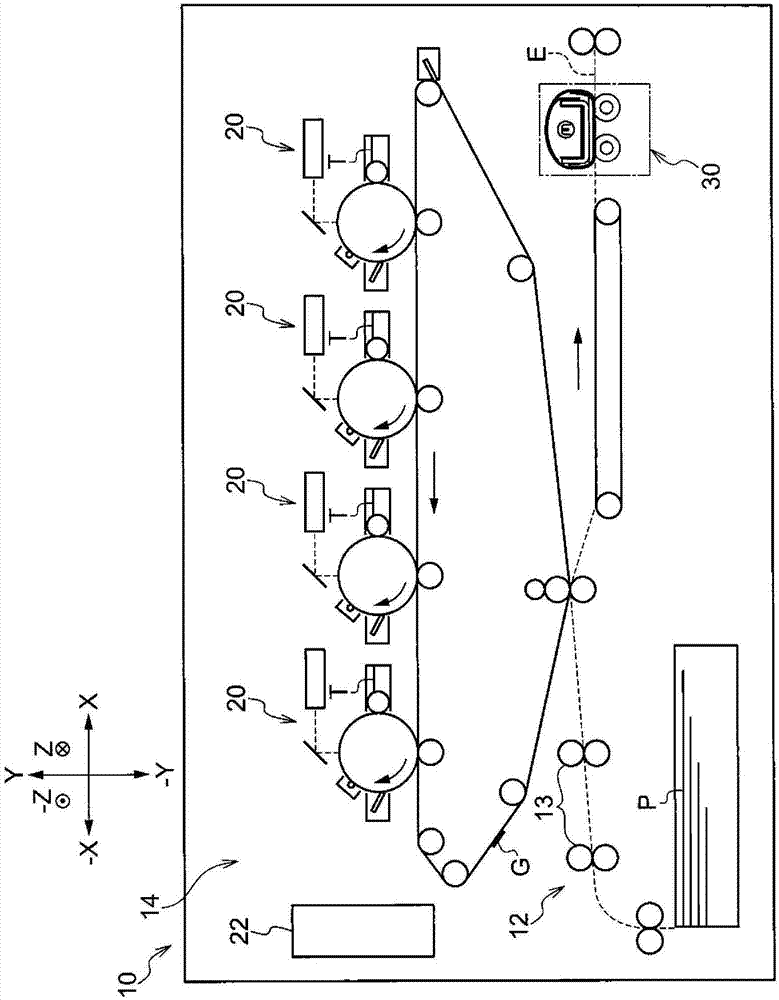
[0031] figure 1 An image forming apparatus 10 according to this exemplary embodiment is shown. The image forming apparatus 10 includes: a conveying section 12 having a roller pair 13 that conveys a sheet of paper P; an image forming section 14 that forms a toner image G; and a fixing device 30 that fixes the formed toner image G to the sheet P by heating and pressing the toner image G. The sheet P is an example of a recording medium. Toner T is an example of a developer. The toner image G is an example of a developer image. The image forming apparatus 14 is an example of a developer image forming unit.

[0032] In the following description, it is assumed that the figure 1 The direction shown by the arrow Y in represents the device height direction, and is determined by figur...


PUM


Abstract

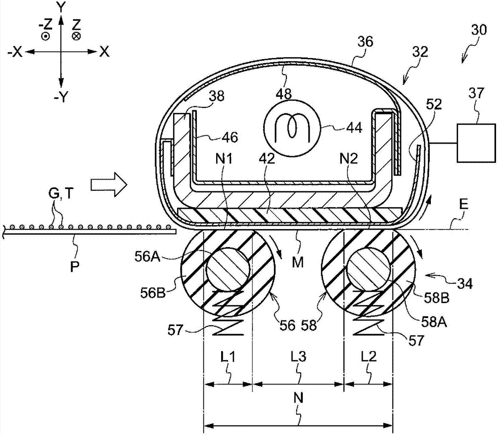
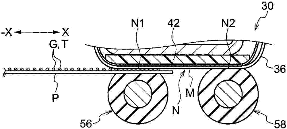
The invention relates to a fixing device and an image forming apparatus. The fixing device includes a heating belt that is provided rotatably around an orthogonal direction orthogonal to a transport direction of a recording medium as an axial direction, and is configured to heat a developer on the recording medium; a support member that is provided inside the heating belt and supports the heating belt; and plural pressing rotational bodies that each are rotatable around the orthogonal direction as an axial direction, are arranged in the transport direction, and are configured to press the heating belt and the recording medium toward the support member.

Description

technical field [0001] The present invention relates to a fixing device and an image forming apparatus. Background technique [0002] A fixing device described in Japanese Unexamined Patent Application Laid-Open No. 2015-169893 includes a first fixing member, a second fixing member, a first bite forming member, a driving member, and a second supporting member. The first fixing member conveys the recording medium. The second fixing member contacts the first fixing member. The first bite forming member contacts the inner side of the first fixing member. The driving member contacts the inner side of the second fixing member and rotatably drives the second fixing member together with the first fixing member. The second supporting member presses the second fixing member against the first bite forming member at a position upstream of the driving member. [0003] In the configuration including the heating belt, the pressing belt contacting the heating belt, and a plurality of p...

Claims


Application Information

Patent Timeline
IPC IPC(8): G03G15/20
CPCG03G15/206G03G15/2064G03G15/2053G03G2215/2025
Inventor 小林丈太后藤康孝森崎想曾雌恭伍古坚浩子
Owner FUJIFILM BUSINESS INNOVATION CORP
Learn More