Rib fracture reduction and fixation apparatus for department of thoracic surgery
A rib fracture and fixation device technology, which is applied in the field of rib fracture anteroposterior fixation device in thoracic surgery, can solve problems such as inability to perform reduction and correction, no positioning structure, difficult reset, etc., achieve fast positioning, improve effective fit, and improve reset effect of effect
- Summary
- Abstract
- Description
- Claims
- Application Information
AI Technical Summary
Problems solved by technology
Method used
Image
Examples
Embodiment 1
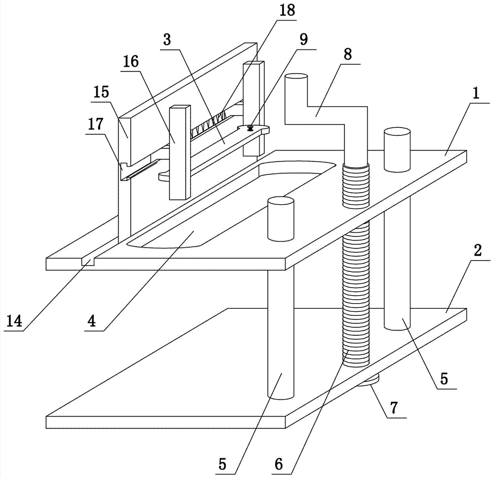
[0031] Such as figure 1 As shown, the present invention comprises upper clamping plate 1, lower clamping plate 2 and fixed plate 3, offers guide hole, threaded hole and first through hole 4 on the upper clamping plate 1, and guide hole and threaded hole are positioned at the right side of upper clamping plate 1 side, the first through hole 4 is located in the middle of the upper clamping plate 1, and the upper end surface of the upper clamping plate 1 is provided with a first chute 14, the extension direction of the first chute 14 is consistent with the extension direction of the ribs during the operation, and the first chute 14 The positioning mechanism is slidingly connected in the groove 14. The positioning mechanism includes a support plate 15 and a clamping plate 16. The lower end of the support plate 15 is slidably matched with the first chute 14. The side end surface of the support plate 15 is provided with a second chute 17. The second chute 17 The cross-section of the...
Embodiment 2
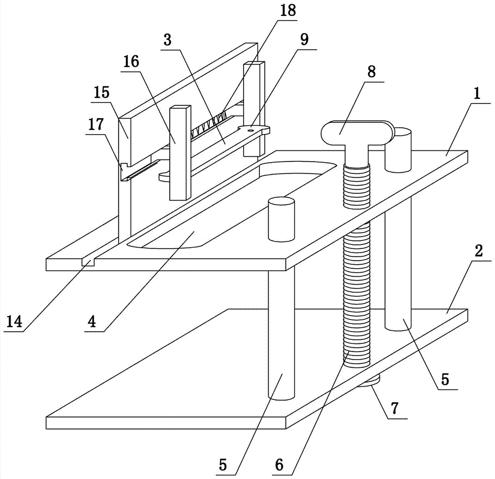
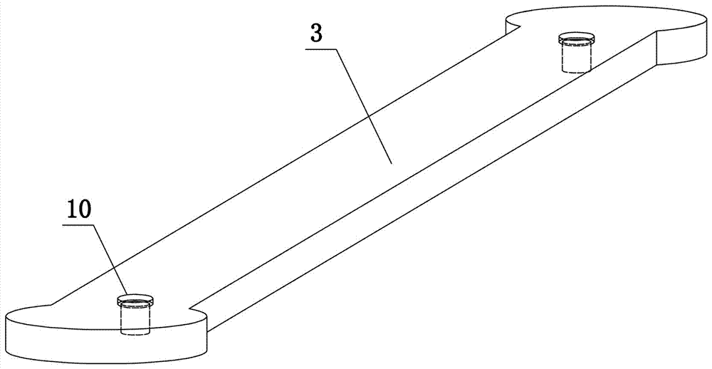
[0033] Such as figure 2 and image 3As shown, the present invention comprises upper clamping plate 1, lower clamping plate 2 and fixed plate 3, offers guide hole, threaded hole and first through hole 4 on the upper clamping plate 1, and guide hole and threaded hole are positioned at the right side of upper clamping plate 1 side, the first through hole 4 is located in the middle of the upper clamping plate 1, and the upper end surface of the upper clamping plate 1 is provided with a first chute 14, the extension direction of the first chute 14 is consistent with the extension direction of the ribs during the operation, and the first chute 14 The positioning mechanism is slidingly connected in the groove 14. The positioning mechanism includes a support plate 15 and a clamping plate 16. The lower end of the support plate 15 is slidably matched with the first chute 14. The side end surface of the support plate 15 is provided with a second chute 17. The second chute 17 The cross-...
Embodiment 3
[0036] Such as Figure 4 As shown, the present invention comprises upper clamping plate 1, lower clamping plate 2 and fixed plate 3, offers guide hole, threaded hole and first through hole 4 on the upper clamping plate 1, the upper end surface of upper clamping plate 1 and lower clamping plate 2 The lower end surfaces of the two springs are all fixedly connected to the elastic assembly. In this embodiment, the elastic assembly adopts four springs 11, and a buffer plate 12 is fixedly connected between each two springs. The guide hole and the threaded hole are located on the right side of the upper clamping plate 1. The first The through hole 4 is located in the middle of the upper clamping plate 1, and the upper end surface of the upper clamping plate 1 is provided with a first chute 14. The extension direction of the first chute 14 is consistent with the extension direction of the ribs in the operation, and the first chute 14 slides Connect the positioning mechanism, the posit...
PUM
 Abstract
Description
Claims
Application Information
 - R&D
- Intellectual Property
- Life Sciences
- Materials
- Tech Scout
- Unparalleled Data Quality
- Higher Quality Content
- 60% Fewer Hallucinations
Browse by: Latest US Patents, China's latest patents, Technical Efficacy Thesaurus, Application Domain, Technology Topic, Popular Technical Reports.
© 2025 PatSnap. All rights reserved.Legal|Privacy policy|Modern Slavery Act Transparency Statement|Sitemap|About US| Contact US: help@patsnap.com


