An anteroposterior fixation device for rib fractures in thoracic surgery

A rib fracture and fixation device technology, which is applied in the field of clinical medicine, can solve problems such as inability to perform reduction and correction, no positioning structure, and inaccurate reset, and achieve the effects of fast positioning, improved effective fit, and enhanced adaptability

Active Publication Date: 2019-06-18
NANYANG CITY CENT HOSPITAL
View PDF2 Cites 0 Cited by
  • Summary
  • Abstract
  • Description
  • Claims
  • Application Information

AI Technical Summary

Problems solved by technology

[0006] The disadvantages of the above two structures are: due to the small cross-sectional area of ​​the ribs, the ribs can only be fixed by the fixation plate or the bone plate, and the reduction and correction cannot be performed, so there is a problem of difficult or inaccurate reduction. When fixing, there is no corresponding positioning structure

Method used


Image

  • An anteroposterior fixation device for rib fractures in thoracic surgery
  • An anteroposterior fixation device for rib fractures in thoracic surgery
  • An anteroposterior fixation device for rib fractures in thoracic surgery

Examples


Embodiment 1

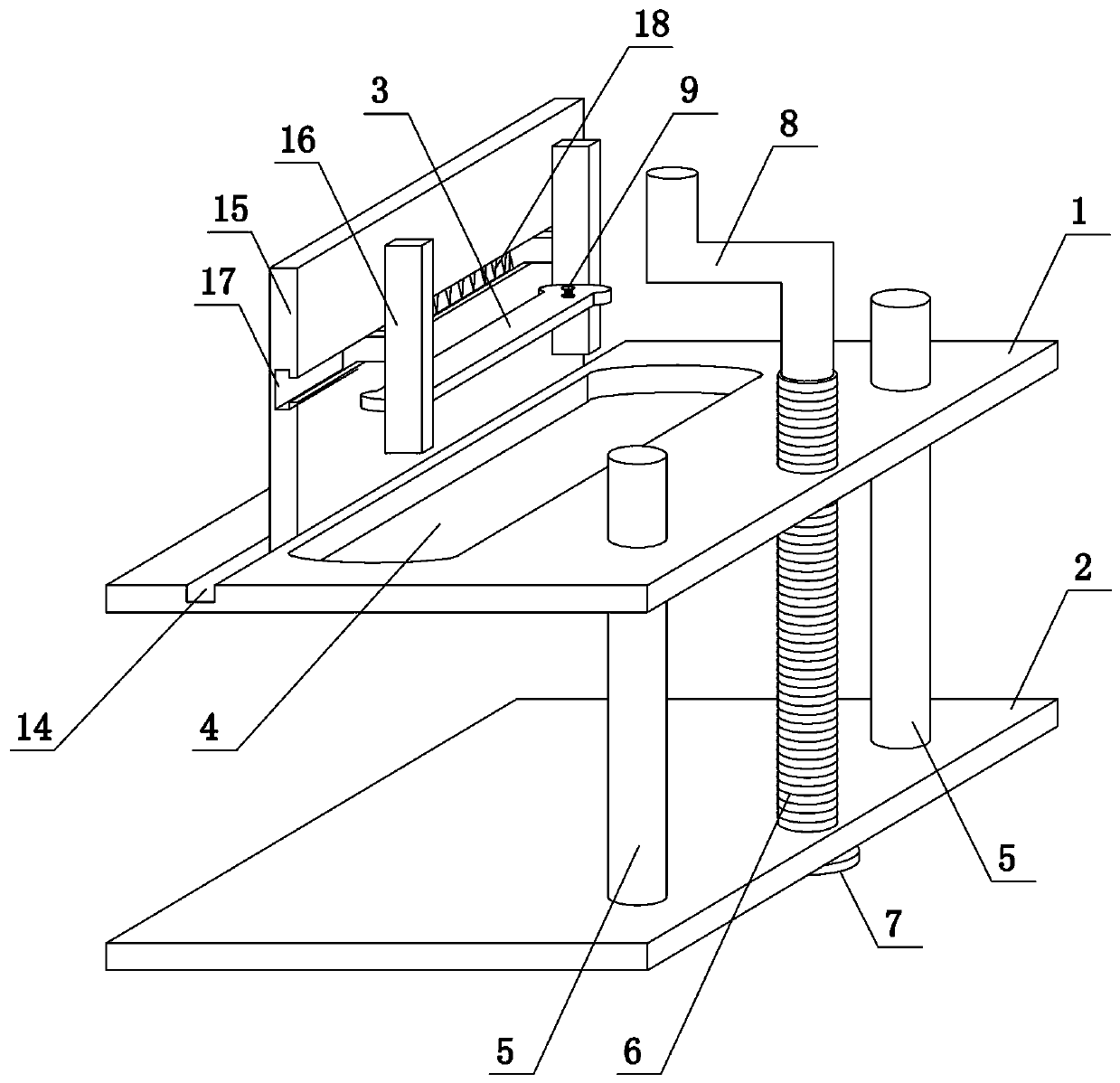
[0031] like figure 1 As shown, the present invention comprises upper clamping plate 1, lower clamping plate 2 and fixed plate 3, offers guide hole, threaded hole and first through hole 4 on the upper clamping plate 1, and guide hole and threaded hole are positioned at the right side of upper clamping plate 1. side, the first through hole 4 is located in the middle of the upper clamping plate 1, and the upper end surface of the upper clamping plate 1 is provided with a first chute 14, the extending direction of the first chute 14 is consistent with the extending direction of the ribs during the operation, and the first chute 14 The positioning mechanism is slidingly connected in the groove 14. The positioning mechanism includes a support plate 15 and a splint 16. The lower end of the support plate 15 is slidably matched with the first chute 14. The side end surface of the support plate 15 is provided with a second chute 17. The second chute 17 The section of the clamping plate ...

Embodiment 2

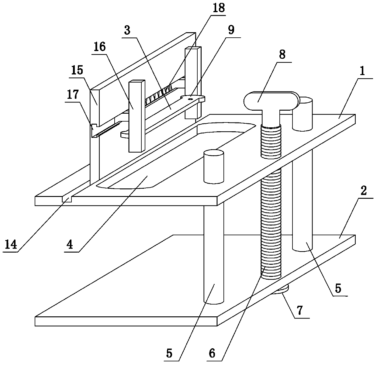
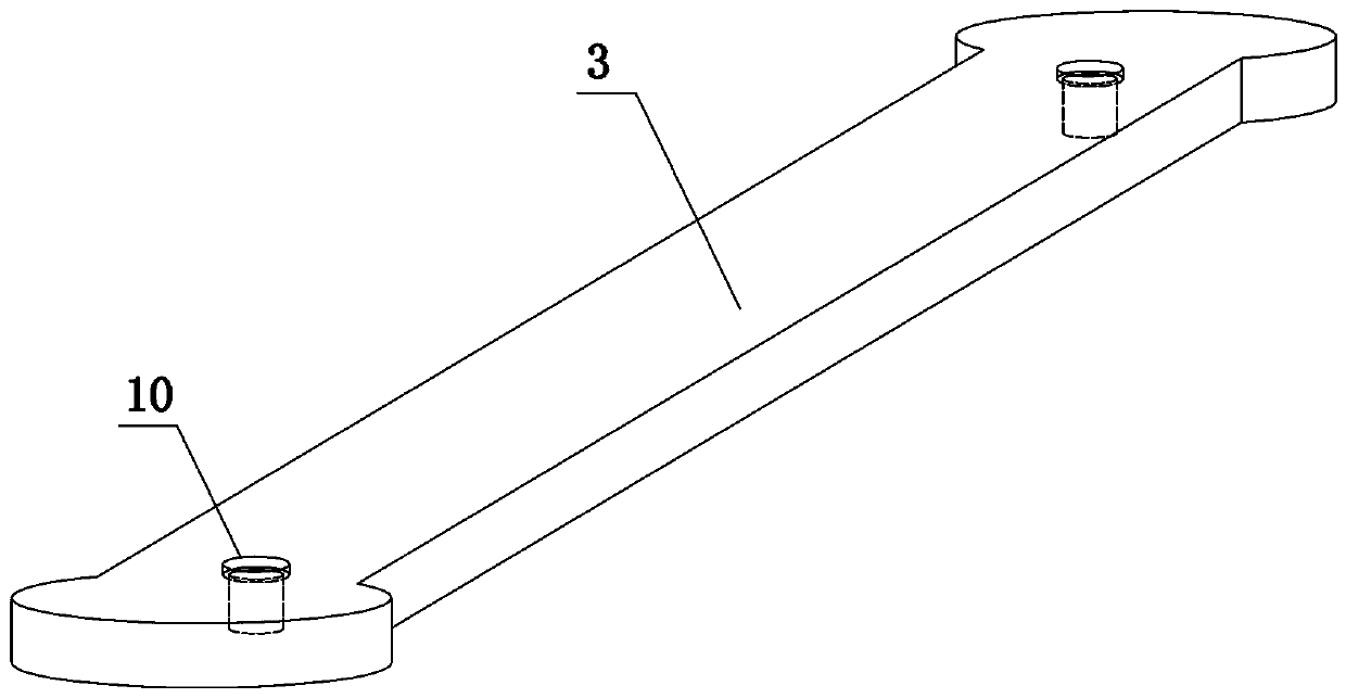
[0033] like figure 2 and image 3As shown, the present invention comprises upper clamping plate 1, lower clamping plate 2 and fixed plate 3, offers guide hole, threaded hole and first through hole 4 on the upper clamping plate 1, and guide hole and threaded hole are positioned at the right side of upper clamping plate 1 side, the first through hole 4 is located in the middle of the upper clamping plate 1, and the upper end surface of the upper clamping plate 1 is provided with a first chute 14, the extension direction of the first chute 14 is consistent with the extension direction of the ribs during the operation, and the first chute 14 The positioning mechanism is slidingly connected in the groove 14. The positioning mechanism includes a support plate 15 and a clamping plate 16. The lower end of the support plate 15 is slidably matched with the first chute 14. The side end surface of the support plate 15 is provided with a second chute 17. The second chute 17 The cross-sec...

Embodiment 3

[0036] like Figure 4 As shown, the present invention comprises upper clamping plate 1, lower clamping plate 2 and fixed plate 3, offers guide hole, threaded hole and first through hole 4 on the upper clamping plate 1, the upper end surface of upper clamping plate 1 and lower clamping plate 2 The lower end surfaces of the two springs are all fixedly connected to the elastic assembly. In this embodiment, the elastic assembly adopts four springs 11, and a buffer plate 12 is fixedly connected between each two springs. The guide hole and the threaded hole are located on the right side of the upper clamping plate 1. The first The through hole 4 is located in the middle of the upper clamping plate 1, and the upper end surface of the upper clamping plate 1 is provided with a first chute 14. The extension direction of the first chute 14 is consistent with the extension direction of the ribs in the operation, and the first chute 14 slides Connect the positioning mechanism, the position...


PUM


Abstract

The invention belongs to the technical field of medical apparatuses for department of thoracic surgery, and in particular discloses a rib fracture reduction and fixation apparatus for department of thoracic surgery. The apparatus comprises an upper clamping plate and a lower clamping plate, wherein guide holes, a threaded hole and a first through hole are formed in the upper clamping plate; a first sliding groove is formed in the upper end face of the upper clamping plate; a locating mechanism is connected into the first sliding groove in a sliding mode; the locating mechanism comprises a supporting plate and splints; guide pillars are fixedly connected to the upper end face of the lower clamping plate; the upper ends of the guide pillars run through the guide holes; a second through hole is formed in the lower clamping plate; a screw rod is rotatably connected into the second through hole; the lower end of the screw rod runs through the lower clamping plate and then is provided with a limiting block; and the upper end of the screw rod runs through the threaded hole and is provided with a rotary piece. According to the rib fracture reduction and fixation apparatus provided by the invention, reduction is implemented on a fracture part by virtue of the upper clamping plate and the lower clamping plate, then a position of rib drilling is determined by virtue of the locating mechanism, and two sides of the fracture part are fixed by virtue of fixing plates, so that an operation integrating reduction, locating and fixation is implemented; and a postoperative recovery effect of a patient is enhanced.

Description

technical field [0001] The invention belongs to the technical field of clinical medicine, in particular to a rib fracture fixation device for thoracic surgery. Background technique [0002] Thoracic surgery, as an important department in a general hospital, specializes in diagnosing and treating the thoracic cavity and its internal organs. According to statistics, the incidence of sternal fractures accounts for 1.0% to 5.5% of thoracic trauma, and the main causes are traffic accidents and construction accidents. It can occur anywhere on the sternum, mostly at the ribs. Rib fractures are different from extremity fractures. Limb fractures can be fixed not only by steel plates, but also through auxiliary fixation of the fracture position outside the body. However, rib fractures can only be fixed by internal steel plates, so the ribs are docked and the fractures are fixed accurately during surgery. The degree requirements are extremely high. [0003] At present, the commonly u...

Claims


Application Information

Patent Timeline
Patent Type & Authority Patents(China)
IPC IPC(8): A61B17/66
CPCA61B17/66A61B2017/564
Inventor 卢万里
Owner NANYANG CITY CENT HOSPITAL
Why Eureka
Try Eureka