A rib fracture repair device for thoracic surgery
A technology for rib fractures and surgery, applied in the field of rib fracture repair devices for thoracic surgery, can solve problems such as inability to perform reduction and correction, difficult reduction, and inaccurate reduction, so as to prevent slippage, improve the effect of reduction, and improve effective fit Effect
- Summary
- Abstract
- Description
- Claims
- Application Information
AI Technical Summary
Problems solved by technology
Method used
Image

Examples
Embodiment 1
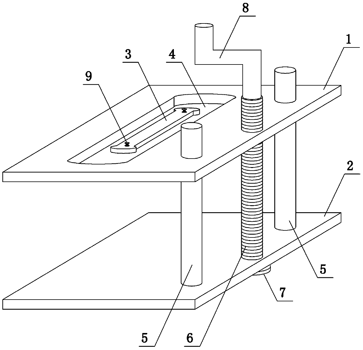
[0031] Such as figure 1 As shown, the present invention comprises upper clamping plate 1, lower clamping plate 2 and fixed plate 3, offers guide hole, threaded hole and first through hole 4 on the upper clamping plate 1, and guide hole and threaded hole are positioned at the right side of upper clamping plate 1 side, the first through hole 4 is located in the middle of the upper clamping plate 1, the upper end surface of the lower clamping plate 2 is fixedly connected to the guide column 5, the guide hole and the guide column 5 are two, and the upper end of the guide column 5 passes through the guide hole and is connected with the guide column 5. The upper clamping plate 1 is slidingly connected, and the second through hole is opened on the lower clamping plate 2, and the second through hole is rotated to connect the screw rod 6. There is one threaded hole, the second through hole and the screw rod 6, and the lower end of the screw rod 6 runs through The lower clamping plate 2...
Embodiment 2
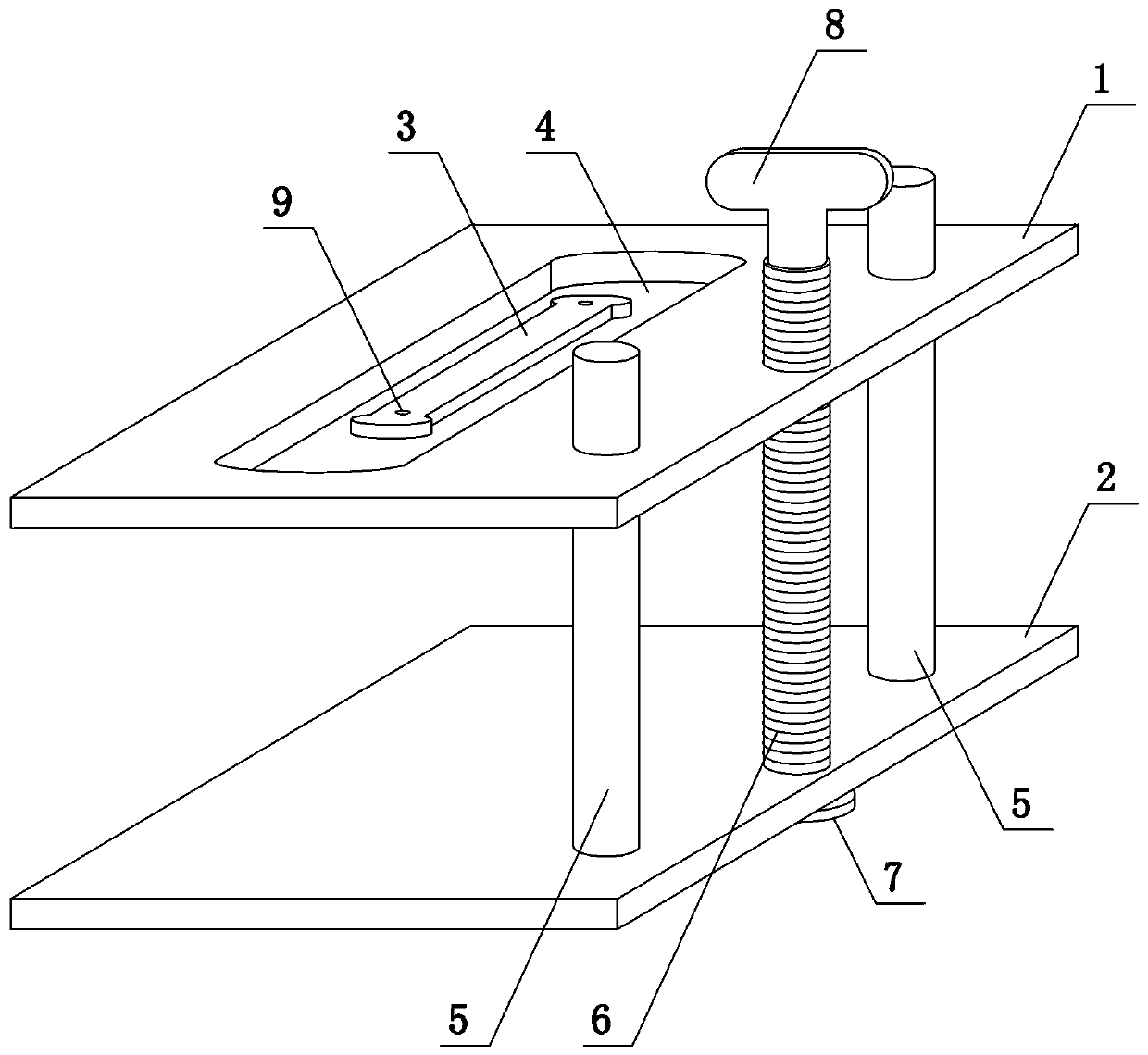
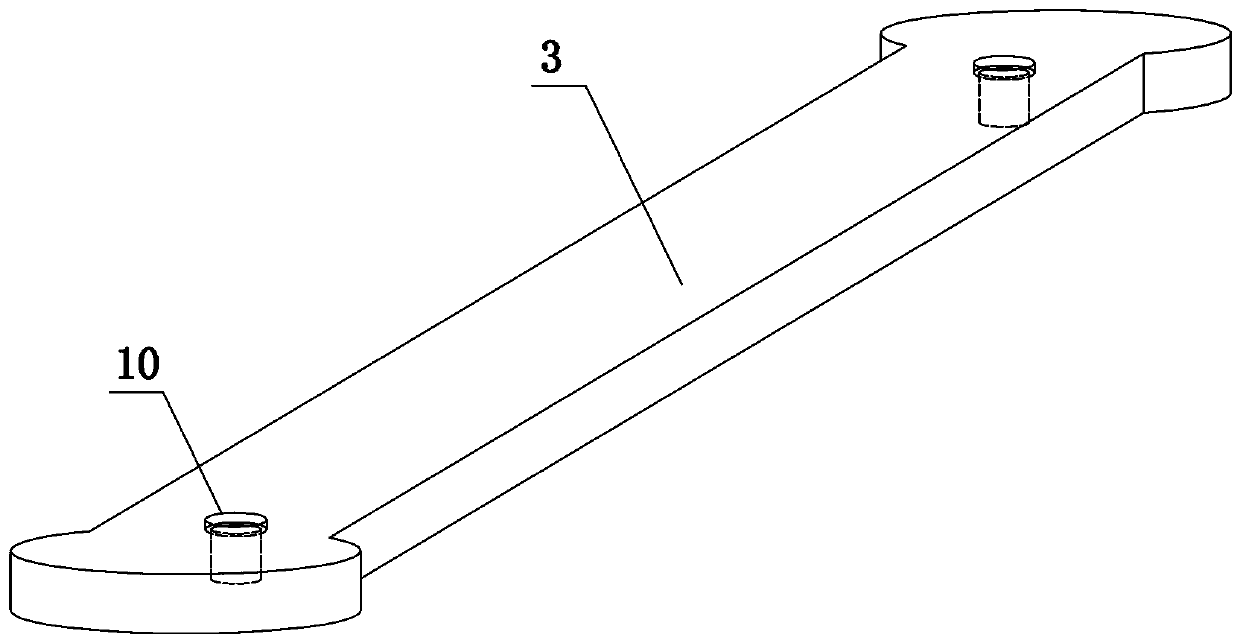
[0033] Such as figure 2 and image 3 As shown, the present invention comprises upper clamping plate 1, lower clamping plate 2 and fixed plate 3, offers guide hole, threaded hole and first through hole 4 on the upper clamping plate 1, and guide hole and threaded hole are positioned at the right side of upper clamping plate 1 side, the first through hole 4 is located in the middle of the upper clamping plate 1, the upper end surface of the lower clamping plate 2 is fixedly connected to the guide column 5, the guide hole and the guide column 5 are two, and the upper end of the guide column 5 passes through the guide hole and is connected with the guide column 5. The upper clamping plate 1 is slidingly connected, and the second through hole is opened on the lower clamping plate 2, and the second through hole is rotated to connect the screw rod 6. There is one threaded hole, the second through hole and the screw rod 6, and the lower end of the screw rod 6 runs through The lower c...
Embodiment 3
[0036] Such as Figure 4 As shown, the present invention comprises upper clamping plate 1, lower clamping plate 2 and fixed plate 3, offers guide hole, threaded hole and first through hole 4 on the upper clamping plate 1, the upper end surface of upper clamping plate 1 and lower clamping plate 2 The lower end surfaces of the two springs are all fixedly connected to the elastic assembly. In this embodiment, the elastic assembly adopts four springs 11, and a buffer plate 12 is fixedly connected between each two springs. The guide hole and the threaded hole are located on the right side of the upper clamping plate 1. The first The through hole 4 is located in the middle of the upper clamping plate 1, and the upper end surface of the lower clamping plate 2 is fixedly connected with the guide post 5. Both the guide hole and the guide post 5 are two, and the upper end of the guide post 5 passes through the guide hole and connects with the upper clamping plate 1 Sliding connection, a...
PUM
 Abstract
Description
Claims
Application Information
 - R&D
- Intellectual Property
- Life Sciences
- Materials
- Tech Scout
- Unparalleled Data Quality
- Higher Quality Content
- 60% Fewer Hallucinations
Browse by: Latest US Patents, China's latest patents, Technical Efficacy Thesaurus, Application Domain, Technology Topic, Popular Technical Reports.
© 2025 PatSnap. All rights reserved.Legal|Privacy policy|Modern Slavery Act Transparency Statement|Sitemap|About US| Contact US: help@patsnap.com