Cleaning equipment

A kind of cleaning equipment and cleaning technology, applied in the field of cleaning, can solve the problems of affecting the cleaning progress, easily damaged equipment, time-consuming and labor-intensive, etc., and achieve the effect of simple structure, convenient operation, and improving the safety of equipment use

Active Publication Date: 2017-09-15
浙江嘉苑园艺景观有限公司
View PDF5 Cites 6 Cited by
  • Summary
  • Abstract
  • Description
  • Claims
  • Application Information

AI Technical Summary

Problems solved by technology

The traditional cleaning method uses a brush head to sweep dust, and then cleans it with a special cleaning agent. This method is very troublesome, time-consuming and laborious, and is easy to damage the equipment. Manual replacement is required, affecting cleaning progress

Method used


Image

  • Cleaning equipment
  • Cleaning equipment
  • Cleaning equipment

Examples


Embodiment Construction

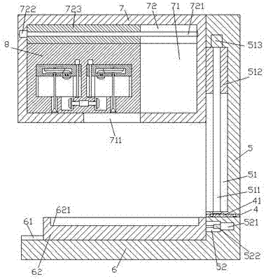
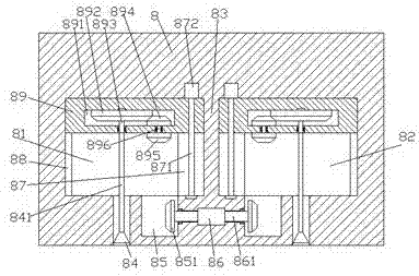
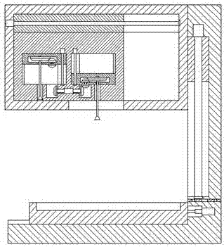
[0023] Such as Figure 1-Figure 6As shown, a cleaning device of the present invention includes a frame composed of a base 6 and a vertical column 5, and a transition device 7 arranged in the frame, and a transition chamber 71 is provided inside the transition device 7. The top wall of the transition chamber 71 extends left and right and is provided with a first sliding groove 72, and the first sliding groove 72 is provided with a first screw rod 721 extending left and right, and the first screw rod 721 is connected with a first sliding groove. Transport block 723, the midpoint of the bottom end surface of the transition device 7 is provided with a top and the transition cavity 71 piercing groove 711, and the transition cavity 71 is provided with a top and the bottom of the first sliding block 723 is fixed. The connected cleaning operation device 8, the left and right sides of the cleaning operation device 8 are oppositely provided with a first sliding chamber 81 and a second s...


PUM


Abstract

The invention discloses cleaning equipment. The cleaning equipment comprises a frame body and a change device arranged in the frame body; the frame body comprises a base platform and a vertical column; a change cavity is formed in the change device; a first sliding conveying groove is formed in the inner top wall of the change cavity in a leftward-and-rightward extending manner; a first screw is arranged in the first sliding conveying groove in a leftward-and-rightward extending manner; a first sliding conveying block is connected onto the first screw in a matched manner; a penetrating groove with the top communicating with the change cavity is formed in the central point of the end surface of the bottom of the change device; a cleaning operation device with the top fixedly connected with the bottom of the first sliding conveying block is arranged in the change cavity; a first sliding conveying cavity and a second sliding conveying cavity are oppositely formed in the left side and the right side of the cleaning operation device; a plate piece is arranged between the first sliding conveying cavity and the second sliding conveying cavity; a second sliding conveying groove is formed in the inner wall of one side, close to the plate piece, of each of the first sliding conveying cavity and the second sliding conveying cavity; and a third sliding conveying groove is formed in the inner wall of one side, far away from the plate piece, of each of the first sliding conveying cavity and the second sliding conveying cavity. The cleaning equipment is simple in structure, convenient to operate, high in safety and high in maintenance speed, and the cleaning efficiency and the cleaning accuracy are improved.

Description

technical field [0001] The invention relates to the technical field of cleaning, in particular to cleaning equipment. Background technique [0002] Printed circuit boards, photoelectric displays and other equipment will be covered with dust after a long time of use. If there is too much dust or the air humidity is high, it will cause corrosion and short circuit to the circuit board, damage parts and internal systems, so regular cleaning and maintenance are required. . The traditional cleaning method uses a brush head to sweep dust, and then cleans it with a special cleaning agent. This method is very troublesome, time-consuming and laborious, and is easy to damage the equipment. It needs to be replaced manually, which affects the cleaning progress. Contents of the invention [0003] The technical problem to be solved by the present invention is to provide a cleaning device, which can solve the above-mentioned problems in the prior art. [0004] The present invention is ...

Claims


Application Information

Patent Timeline
Patent Type & Authority Applications(China)
IPC IPC(8): B08B6/00
CPCB08B6/00
Inventor 孙美娟
Owner 浙江嘉苑园艺景观有限公司
Why Eureka
Try Eureka