
Product closed end bending, chamfering and angle shoveling die

A closed-end, product technology, applied in the field of stamping dies, can solve problems such as affecting appearance, affecting assembly, and related parts separation, and achieves the effect of convenient and quick demoulding

Active Publication Date: 2017-09-15
佛山市顺德区富润华模具有限公司
View PDF8 Cites 0 Cited by
  • Summary
  • Abstract
  • Description
  • Claims
  • Application Information

AI Technical Summary

Problems solved by technology

[0002] The processing technology of traditional technology for pre-coated panels generally includes trimming and punching, folding four sides and bending U. The disadvantage of this sheet metal stamping process is that when the end edge is bent first in the second sequence, if it is bent U again, Due to the flow of materials, the U-shaped rounded corners are bent outwards (referred to as "extruded"), which seriously affects the appearance requirements of the product; after the pre-coated board is formed, it is directly sent to the assembly line for assembly without any treatment, so the end face is absolutely not allowed There are phenomena such as scratches or waves, and the main factor causing scratches on the end face of the fillet is that the gap between the punch and die is too small during the shovel bending process, but if the gap is large, waves will be generated on the end face, which will affect the assembly and cause it to be separated from the related parts , seriously affect the appearance, and the prior art has not solved the above problems

Method used


Image

  • Product closed end bending, chamfering and angle shoveling die
  • Product closed end bending, chamfering and angle shoveling die
  • Product closed end bending, chamfering and angle shoveling die

Examples


Embodiment Construction

[0048] The present invention will be further described below with reference to the drawings and embodiments.

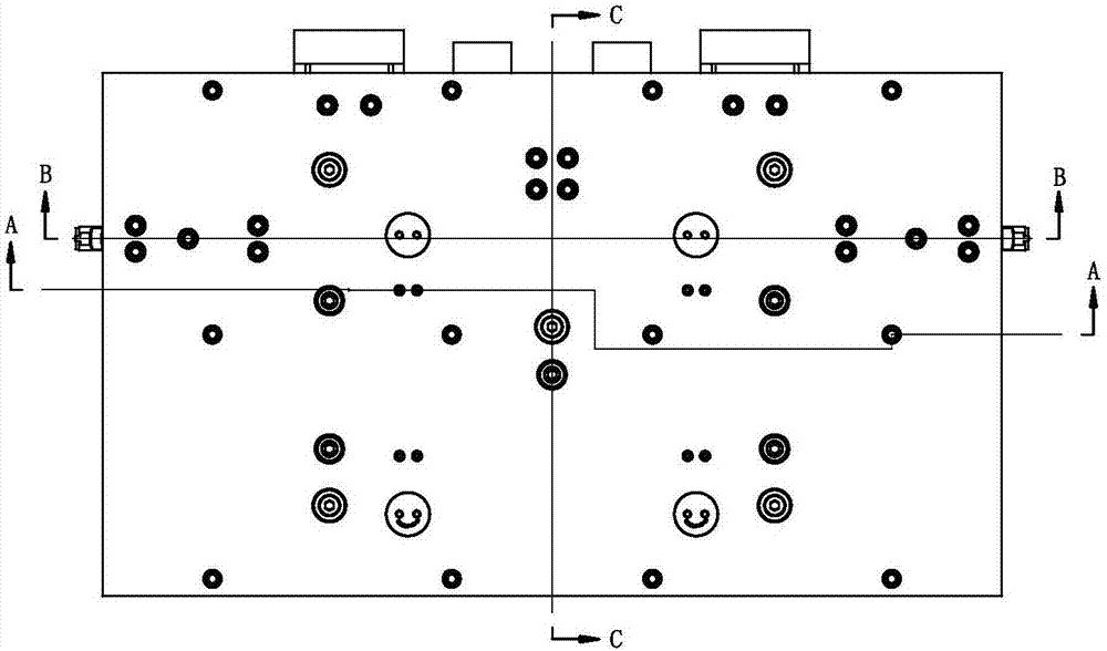
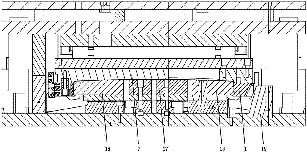
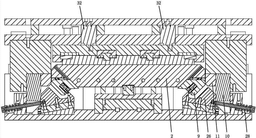
[0049] See Figure 1-Figure 26 , The closed-end folding and shovel corner mold of this product is mainly used for processing refrigerator door panels, specifically to bend the edge of the refrigerator door panel to generate flanging d1, first corner d2 and second corner d3. The mold includes an upper mold assembly and a lower mold assembly corresponding to each other up and down; a pressing mechanism and an end folding mechanism are arranged between the upper mold assembly and the lower mold assembly; the specific structures are as follows:

[0050] The pressing mechanism includes a driving punch 17, two side pressing punches 18, two side pressing plates 1, a sliding plate 22, a first upper wedge 6 and a first lower wedge 23, and the two side pressing punches 18 are respectively arranged on the driving punch On both sides of 17, the pressing plates 1 on both sides are res...


PUM


Abstract

The invention relates to a product closed end bending, chamfering and angle shoveling die. The product closed end bending, chamfering and angle shoveling die comprises an upper die assembly and a lower die assembly which vertically correspond to each other. A compressing mechanism, an end bending mechanism and a side beating mechanism are arranged between the upper die module and the lower die module. The compressing mechanism comprises a drive male die, a side pressing male die, a side pressing plate, a sliding plate, a first upper wedge and a first lower wedge. The end bending mechanism comprises a side bending female die, an angle bending female die, a wrap angle female die, a second upper wedge and a third upper wedge. The side beating mechanism comprises a side beating wedge and a side beating drive block. The product closed end bending, chamfering and angle shoveling die has the beneficial effects that the angle bending female die moves in the direction of 45 degrees, surplus materials flow inwards, and the phenomenon that the U-shaped circular bead end is convexly bent outwards is completely avoided; a gap stepless variable structure is arranged, after end bending is carried out, a gap between a first flush surface and a second flush surface is equal to one time of material thickness, and the wave phenomenon is avoided; and the longitudinal motion of the drive male die is converted into the lateral motion of the side pressing male die, top damage is effectively avoided, and die removing is more convenient.

Description

Technical field [0001] The invention relates to a stamping die, in particular to a product closed-end folding shovel corner die. Background technique [0002] The processing technology of the traditional technology for the pre-coated plate generally includes trimming and punching, folding four sides and bending U. The disadvantage of this sheet metal stamping process is that after the second sequence is the first bending of the end edge, if the U is again bent, Due to the flow of material, the U-shaped rounded end is folded and convex (referred to as “convex”), which seriously affects the appearance requirements of the product; after the pre-coated plate is formed, it is directly sent to the assembly line for assembly, so the end face is absolutely not allowed There are scratches or waves, and the main factor that causes scratches on the end face of the rounded part is that the gap between the convex and concave molds is too small during the shovel bending process, but if the gap...

Claims


Application Information

Patent Timeline
IPC IPC(8): B21D37/10B21D19/00
Inventor 郭意凌
Owner 佛山市顺德区富润华模具有限公司
Learn More