Mechanical paw with limiting device

A technology of manipulator claw and limit device, which is applied to manipulators, chucks, manufacturing tools, etc., can solve the problems of inability to grasp and capture, unable to provide relative state information, etc., and achieve fast, reliable and stable grasping and releasing, simple structure, The effect of fast penetrating piercing

Inactive Publication Date: 2017-09-15
FOSHAN ZHENGLUE INFORMATION TECH CO LTD
View PDF5 Cites 23 Cited by
  • Summary
  • Abstract
  • Description
  • Claims
  • Application Information

AI Technical Summary

Problems solved by technology

At present, the robot gripper cannot provide its relative state informat

Method used


Image

  • Mechanical paw with limiting device

Examples


Embodiment Construction

[0013] The following will clearly and completely describe the technical solutions in the embodiments of the present invention with reference to the accompanying drawings in the embodiments of the present invention. Obviously, the described embodiments are only some, not all, embodiments of the present invention. Based on the embodiments of the present invention, all other embodiments obtained by persons of ordinary skill in the art without making creative efforts belong to the protection scope of the present invention.

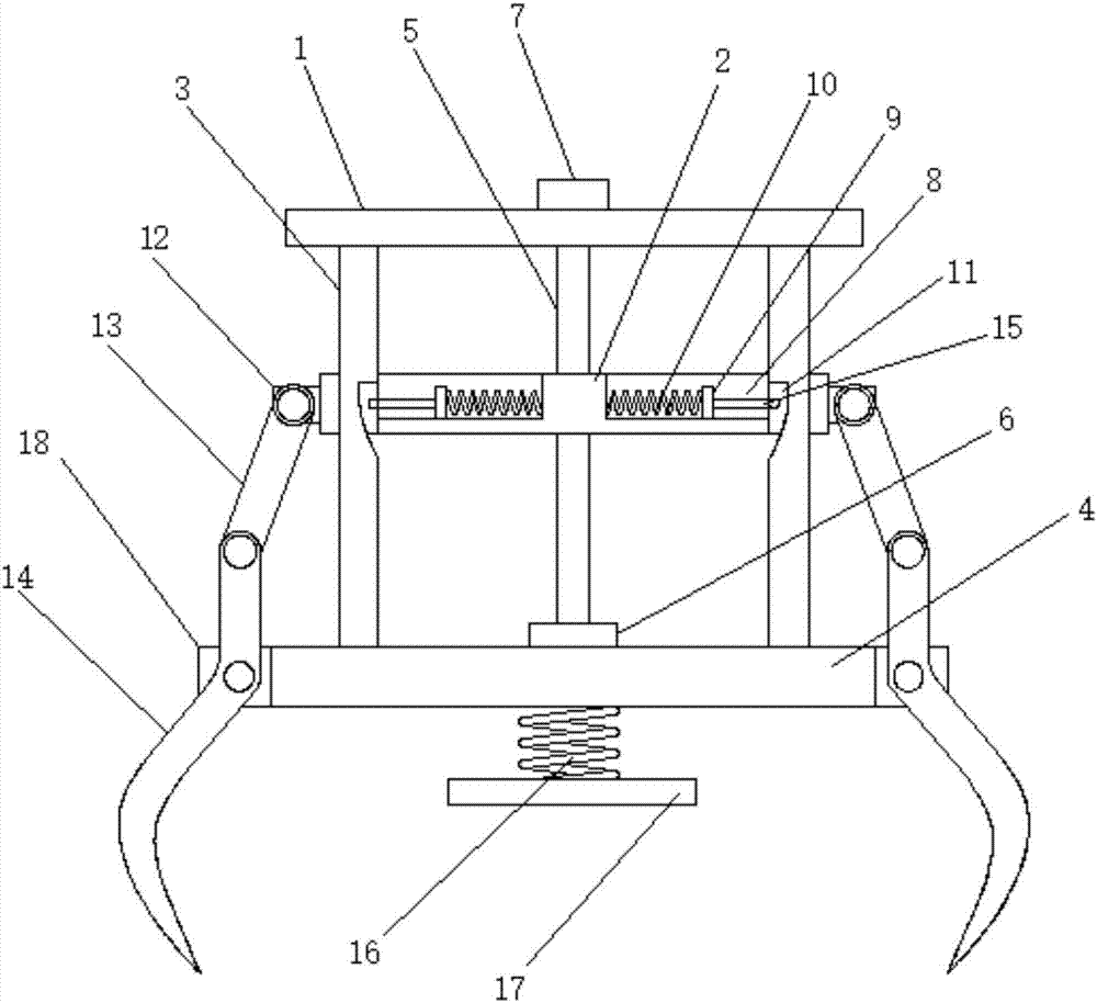
[0014] see figure 1 , in an embodiment of the present invention, a mechanical gripper with a limit device includes an upper disk 1, a push disk 2 and a chassis 4, the push disk 2 is located between the upper disk 1 and the chassis 4, and the upper disk 1 The side of the lower end surface is provided with a plurality of fixed rods 3 that pass through the push plate 2 and are fixedly connected to the upper end surface of the chassis 4, and the center of the uppe...


PUM


Abstract

The invention discloses a mechanical paw with a limiting device. The mechanical paw comprises an upper disc, a pushing disc and a bottom disc. The center of the upper disc is provided with a screw rod penetrating through the pushing disc. The pushing disc is provided with limiting siding grooves in one-to-one correspondence with fixing rods. Each limiting siding groove is internally provided with a sliding plate slidably connected with the limiting siding groove. One side of each sliding plate is connected with the inner wall of the corresponding limiting siding groove through a limiting spring, and the other end of each sliding plate is provided with a limiting rod. The side of the pushing disc is provided with a plurality of first hinged frames arranged in a circular ring mode. The side of the bottom disc is provided with a plurality of second hinged frames. Each first hinged frame is provided with a connecting rod of which one end is hinged to the first hinged frame. Each second hinged frame is provided with a hook paw of which the middle is hinged to the second hinged frame. The top end of each hook paw is hinged to the lower end of the corresponding connecting rod. The mechanical paw with the limiting device is simple in structure, can achieve firmly grabbing and releasing of targets rapidly, reliably and stably, and has the functions of landing buffering, rapid penetration and puncturing, grabbing and the like.

Description

technical field [0001] The invention relates to a mechanical arm, in particular to a mechanical claw with a limiting device. Background technique [0002] The robot gripper is a highly integrated electromechanical system with multiple sensing functions in the design of the robot. It is not only a sensor that actively perceives the information of the working environment, but also an actuator at the end of the robot. The analysis of the structure of the claw workpiece, the determination of the positioning point and clamping method of the workpiece, the determination of the position and quantity of the workpiece detection sensor, the cleaning of the workpiece surface, the safety of the gripper and other related design requirements. At present, the robot gripper cannot provide its relative state information, and cannot realize fast, stable and reliable grasping and capture. Contents of the invention [0003] The purpose of the present invention is to provide a mechanical grip...

Claims


Application Information

Patent Timeline
IPC IPC(8): B25J15/02
CPCB25J15/0206
Inventor 肖路长
Owner FOSHAN ZHENGLUE INFORMATION TECH CO LTD
Why Eureka
Try Eureka