
Foam cutting machine

A cutting machine and foam technology, applied in metal processing and other directions, can solve problems such as low safety factor, poor mold applicability, delay time, etc., and achieve the effect of ensuring no need to repair, control production speed, and facilitate cutting control.

Pending Publication Date: 2017-09-15
浙江泰瑞重型机械有限公司
View PDF8 Cites 2 Cited by
  • Summary
  • Abstract
  • Description
  • Claims
  • Application Information

AI Technical Summary

Problems solved by technology

[0002] At present, there are many models and specifications of foam splitters on the market, with X.Y axial maximum cutting range control. For molds with complex mechanisms and many cavity surfaces, the applicability is poor, the price is expensive, the practicability is not strong, and the pertinence is too strong, so it cannot be widely used. To meet all the requirements of customers, relevant supporting fixtures need to be customized
With the development of science and technology, in order to increase the price, the word NC is added blindly. The NC foam cutting machine in the market has high cost, low practicability, and low safety factor. The foam itself is also an easy item. High-temperature heat conduction, the safety factor is naturally low. As a company's research and development product, it is impossible to produce products in batches. Although it can save time and cost by buying a CNC one, compared to the operation of a single component, it seems to delay time.

Method used


Image

  • Foam cutting machine

Examples


Embodiment Construction

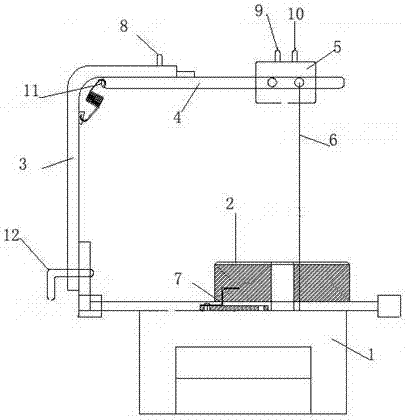
[0013] Combine below figure 1 Specific description embodiment:

[0014] The foam cutting machine includes a workbench 1, the workbench 1 is provided with a rotary adjustment disc 2, one side of the workbench 1 is provided with a single gantry Y-axis 3, and the upper end of the single gantry Y-axis 3 is provided with a single gantry X axis 4, one end of single gantry X axis 4 is connected with a heating wire adjustment device 5, and the heating wire adjustment device 5 is connected with a heating wire 6, and one end of the heating wire 6 is set on the heating wire adjustment device, and the other end of the heating wire 6 Set on the sliding assembly 7 of the workbench 1, the position of the heating wire 6 on the workbench can be adjusted through the heating wire adjusting device and the sliding assembly.

[0015] Preferably, a heating wire tightness adjusting device 8 is provided between the single gantry Y-axis 3 and the single gantry X-axis 4, and a heating wire fastening de...


PUM


Abstract

The invention belongs to the technical field of foam cutting tools, and particularly relates to a foam cutting machine. The foam cutting machine comprises a workbench, and is characterized in that a rotary adjusting disc is arranged on the workbench; a single gantry shaft Y is arranged on one side of the workbench; a single gantry shaft X is arranged at the upper end of the single gantry shaft Y; one end of the single gantry shaft X is connected with an electric heating wire adjusting device; an electric heating wire is connected to the electric heating wire adjusting device; one end of the electric heating wire is arranged on the electric heating wire adjusting device, and the other end of the electric heating wire is arranged on a sliding assembly of the workbench; and the position of the electric heating wire on the workbench can be adjusted through the electric heating wire adjusting device and the sliding assembly. The foam cutting machine has the beneficial effects that the single part production speed is effectively controlled; the cost is reduced; the quality is improved; and one-time cutting of a complex curved face can be guaranteed, and shaping is not needed.

Description

technical field [0001] The invention belongs to the technical field of foam cutting tools, in particular to a foam cutting machine. Background technique [0002] At present, there are many models and specifications of foam splitters on the market, with X.Y axial maximum cutting range control. For molds with complex mechanisms and many cavity surfaces, the applicability is poor, the price is expensive, the practicability is not strong, and the pertinence is too strong, so it cannot be widely used. To meet all the requirements of customers, the relevant supporting fixtures need to be customized. With the development of science and technology, in order to increase the price, the word NC is added blindly. The NC foam cutting machine in the market has high cost, low practicability, and low safety factor. The foam itself is also an easy item. High-temperature heat conduction, the safety factor is naturally low. As a company's research and development product, it is impossible to ...

Claims


Application Information

Patent Timeline
Patent Type & Authority Applications(China)
IPC IPC(8): B26F3/12B26D7/26
CPCB26D7/2628B26F3/12
Inventor 姚礼贤吴炜煌何英张金荣李立峰
Owner 浙江泰瑞重型机械有限公司
Learn More