Pre-stressing-force fabricated concrete-frame-joint connecting structure and construction method thereof

A node connection and prefabricated concrete technology, which is applied in truss structures, building structures, protective buildings/shelters, etc., can solve the problems of difficult construction of dry connection nodes, poor structural integrity, and complicated construction process. Achieve the effects of enhancing the ability to resist progressive collapse, improving integrity, and improving shear resistance

Pending Publication Date: 2017-09-15
CHINA STATE CONSTRUCTION ENGINEERING CORPORATION +1
View PDF5 Cites 48 Cited by
  • Summary
  • Abstract
  • Description
  • Claims
  • Application Information

AI Technical Summary

Problems solved by technology

[0006] The technical problems to be solved are: the construction process of the existing semi-dry prefabricated concrete frame structure connection nodes

Method used


Image

  • Pre-stressing-force fabricated concrete-frame-joint connecting structure and construction method thereof
  • Pre-stressing-force fabricated concrete-frame-joint connecting structure and construction method thereof
  • Pre-stressing-force fabricated concrete-frame-joint connecting structure and construction method thereof

Examples


Embodiment 1

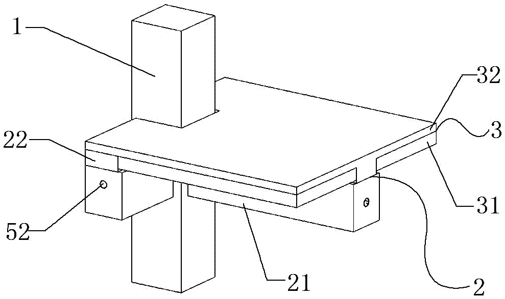
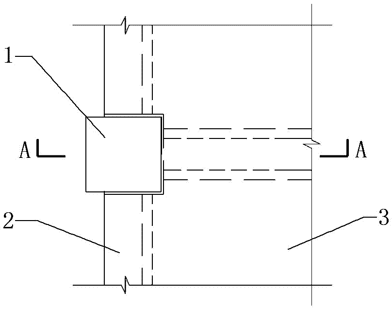
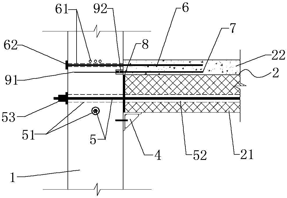
[0046] Such as Figure 1 to Figure 3 As shown, the prestressed assembled concrete frame node connection structure of the present invention includes a precast concrete column 1, a precast concrete composite beam 2, a composite floor 3, and post-tensioned prestressed steel bars connecting the precast concrete column 1 and the precast concrete composite beam 2 Bundle 5, bending energy dissipation steel bar 6 and shear high-strength steel bar 7 located in the post-casting layer on the upper part of the precast concrete composite beam 2, the post-casting layer 22 of the beam of the precast concrete composite beam 2 and the post-casting layer of the composite floor 3 32 are poured in one piece. The precast concrete column 1 is a side column, and the side wall of the precast concrete column 1 is provided with a temporary support 4, the temporary support 4 is a corbel, and the other side supports the beam bottom of the precast concrete composite beam 2.

[0047] Such as figure 1 As ...

Embodiment 2

[0060] Such as Figure 4 to Figure 9 As shown, the prestressed assembled concrete frame node connection structure of the present invention includes a precast concrete column 1, a precast concrete composite beam 2, a composite floor 3, and post-tensioned prestressed steel bars connecting the precast concrete column 1 and the precast concrete composite beam 2 Bundle 5, bending energy dissipation steel bar 6 and shear high-strength steel bar 7 located in the post-casting layer on the upper part of the precast concrete composite beam 2, the post-casting layer 22 of the beam of the precast concrete composite beam 2 and the post-casting layer of the composite floor 3 32 are poured in one piece. The precast concrete column 1 is the central column, and the side wall of the precast concrete column 1 is provided with a temporary support 4, which is a corbel, and the other side is supported on the beam bottom of the precast concrete composite beam 2.

[0061] Such as Figure 4 and Fi...

Embodiment 3

[0067] Such as figure 1 , figure 2 and Figure 10 As shown, the prestressed assembled concrete frame node connection structure of the present invention includes a precast concrete column 1, a precast concrete composite beam 2, a composite floor 3, and post-tensioned prestressed steel bars connecting the precast concrete column 1 and the precast concrete composite beam 2 Bundle 5, bending energy-dissipating steel bar 6 and shear high-strength steel bar 7 located in the post-casting layer on the upper part of the precast concrete composite beam 2, the post-casting layer 22 of the beam of the precast concrete composite beam 2 and the post-casting layer of the composite floor 3 32 are poured in one piece. The precast concrete column 1 is a side column, and the side wall of the precast concrete column 1 is provided with a temporary support 4, the temporary support 4 is a corbel, and the other side supports the beam bottom of the precast concrete composite beam 2.

[0068]The pr...


PUM

PropertyMeasurementUnit
Compressive strengthaaaaaaaaaa

Abstract

The invention relates to the technical field of fabricated concrete frame structures, and discloses a pre-stressing-force fabricated concrete-frame-joint connecting structure and a construction method thereof. The pre-stressing-force fabricated concrete-frame-joint connecting structure comprises a prefabricated concrete column, a prefabricated concrete superposed beam, a composite floor slab, a post-tensioned pre-stressing tendon, an anti-bending and energy-consuming reinforcing steel bar and a shear-resistant and high-strength reinforcing steel bar, wherein the post-tensioned pre-stressing tendon, the anti-bending and energy-consuming reinforcing steel bar and the shear-resistant and high-strength reinforcing steel bar are connected with the prefabricated concrete column and the prefabricated concrete superposed beam. A beam post-pour layer of the prefabricated concrete superposed beam and a slab post-pour layer of the composite floor slab are poured integrally, the inner portion of a beam column seam between the prefabricated concrete superposed beam and the prefabricated concrete column is filled with high-strength crack-pouring binding materials, the anti-bending and energy-consuming reinforcing steel bar and the shear-resistant and high-strength reinforcing steel bar are laid in the beam post-pour layer of the upper portion of the prefabricated concrete superposed beam, and the anti-bending and energy-consuming reinforcing steel bar is located above the shear-resistant and high-strength reinforcing steel bar. According to the pre-stressing-force fabricated concrete-frame-joint connecting structure and the construction method thereof, efficient construction can be achieved, the anti-seismic property and the progressive-collapse-resistant capability are good, and post-earthquake repairing is facilitated.

Description

technical field [0001] The invention relates to the technical field of assembled concrete frame structures, in particular to a prestressed assembled concrete frame node connection structure and a construction method thereof. Background technique [0002] The prefabricated concrete frame structure system is widely used due to its fast construction speed and good social and environmental benefits. Its seismic performance is mainly determined by the connection nodes between prefabricated components. [0003] At present, the domestic prefabricated concrete frame structure system mainly adopts two methods, one is the semi-dry type, the beam-column is disconnected at the node connection, and the beam-column components are prefabricated in sections, and the connection node area of ​​the beam-column is at the construction site Cast-in-place forms an assembled integral structural system. The connection structure of this node is complex and difficult to construct; one is dry type, whi...

Claims


Application Information

Patent Timeline
IPC IPC(8): E04B1/21E04B1/22E04B1/58E04B1/38E04G21/12
CPCE04B1/21E04B1/22E04B1/38E04B1/58E04B1/5831E04G21/12E04H9/021E04C3/26E04B1/215
Inventor 郭海山齐虎刘康王冬雁李黎明田力达耿娇李明张海涛李桐杨晓杰范昕侯学颖曾涛蒋立红
Owner CHINA STATE CONSTRUCTION ENGINEERING CORPORATION
Why Eureka
Try Eureka