Feed structure, antenna unit and multi-array antenna
An antenna unit, feeding technology, applied in the field of antenna unit, multi-array antenna, and feeding structure, can solve the problems of insufficient radiation performance such as radiation height and gain, insufficient radiation height of antenna structure, poor radiation performance such as gain, etc. To achieve the effect of being conducive to large-scale, compact structure and low cost
Pending Publication Date: 2017-09-15
TONGYU COMM INC
View PDF6 Cites 7 Cited by
- Summary
- Abstract
- Description
- Claims
- Application Information
AI Technical Summary
Problems solved by technology
[0003] The main purpose of the present invention is to provide a feed structure to solve the problems of insufficient radiation height, complex structure, large size, high cost, and poor radiation performance such as gain of the existing antenna structure.
[0004] Another object of the present invention is to provide a new type of antenna unit to solve the existing antenna complex structure, large size, high cost, insufficient radiation performance such as radiation height and gain, etc.
[0005] Another object of the present invention is to provide a multi-array antenna to solve the problems of antenna capacity, space, antenna radiation performance and cost required by dense high-rise buildings
Method used
View moreImage
Smart ImageViewing Examples

Examples
Embodiment approach
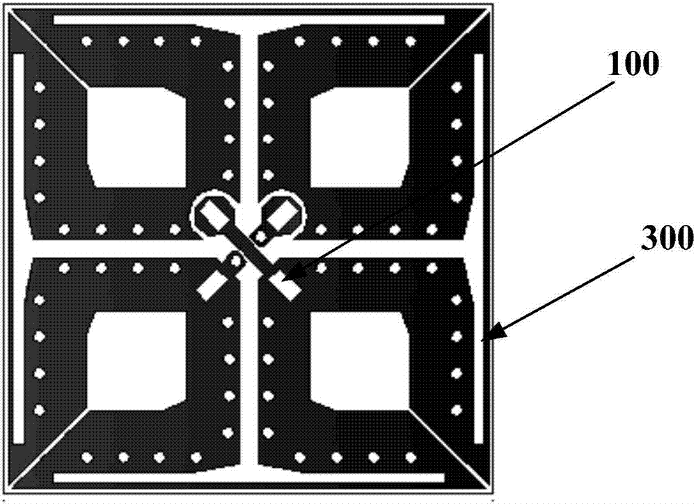
[0060] As an implementation manner, the multi-array antenna 500 is a building coverage antenna.
Login to View More PUM
 Abstract
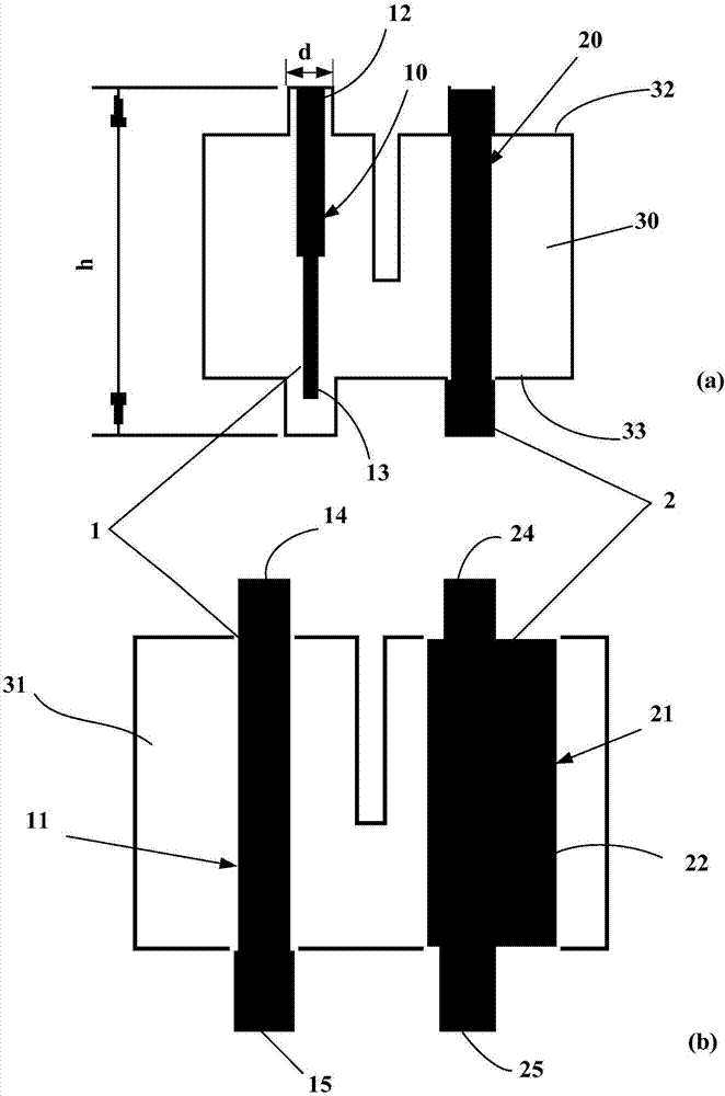
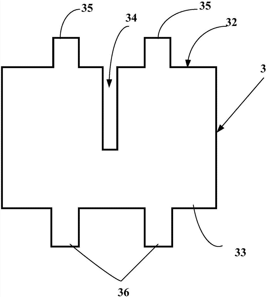
The invention discloses a feed structure, an antenna unit and a multi-array antenna. The feed structure comprises supporting sheets and feed baluns; the maximum height of each supporting sheet is 16-19mm in the vertical direction; the feed balun is attached to the surface of the corresponding supporting sheet in the vertical direction; and each feed balun comprises a positive electrode balun and a grounding balun. By means of thinning the positive electrode balun and thickening the grounding balun, the optimized antenna performance can be obtained, and the compact antenna structure and the large-scale antenna are formed.
Description
technical field [0001] The invention mainly relates to the field of wireless communication, in particular to a feeding structure, an antenna unit and a multi-array antenna. Background technique [0002] With the rapid development of economy and urban construction, high-rise buildings are becoming more and more dense, the height of buildings is also increasing, and users are dense. Wireless communication in high-rise buildings has problems such as signal coverage, signal strength, and communication capacity, and has higher requirements for the number, capacity, and radiation performance of building coverage antennas. The existing antenna structure cannot meet the height requirement, the cost is high, the structure is complex and bulky, and the radiation performance is insufficient. Contents of the invention [0003] The main purpose of the present invention is to provide a feeding structure to solve the problems of insufficient radiation height, complex structure, large si...
Claims
Login to View More Application Information
Patent Timeline
 Patent Type & Authority Applications(China)
IPC IPC(8): H01Q1/36H01Q1/38H01Q1/50H01Q21/24
CPCH01Q1/36H01Q1/38H01Q1/50H01Q21/24
Inventor 朱彬彬高卓锋吴中林赵伟周定
Owner TONGYU COMM INC