
Mixing feet including flanges that allow the mixing feet to be removably mounted on the housing

A technology of stirring feet and flanges, which is applied in the field of stirring feet, can solve the problems of no description of flanges, no description of flange pull-out resistance, etc., and achieve the effects of simple assembly, improved metal characteristics, and increased value

Active Publication Date: 2022-05-24
SEB SA
View PDF10 Cites 0 Cited by
  • Summary
  • Abstract
  • Description
  • Claims
  • Application Information

AI Technical Summary

Problems solved by technology

[0004] However, this document does not describe how the flange is fixed axially on the upper end of the barrel and in particular how the pull-out resistance of the flange is obtained

Method used


Image

  • Mixing feet including flanges that allow the mixing feet to be removably mounted on the housing
  • Mixing feet including flanges that allow the mixing feet to be removably mounted on the housing
  • Mixing feet including flanges that allow the mixing feet to be removably mounted on the housing

Examples


Embodiment Construction

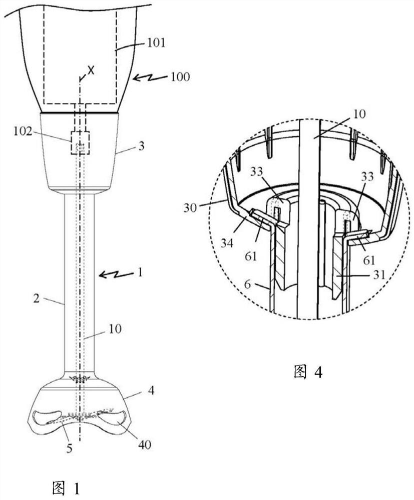
[0028] Only elements necessary to understand the invention are shown. In order to facilitate reading of the figures, the same elements are given the same reference numerals in different figures.

[0029] It is also worth noting that, in this document, the terms "lower", "upper", "high", "low" used to describe the stirring feet refer to when the stirring feet are arranged vertically and their protective cover is facing The stirring foot in use when oriented downward.

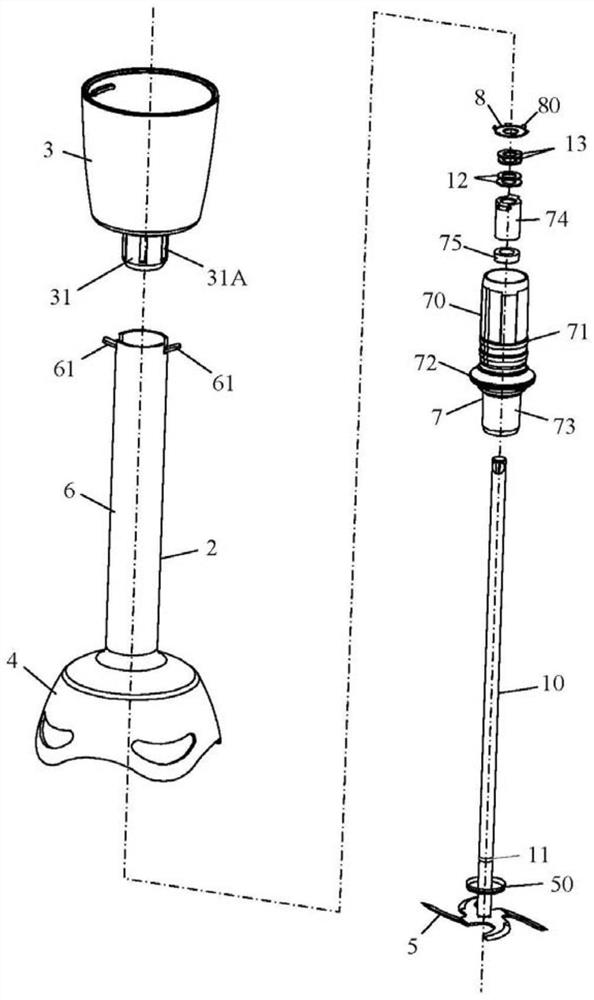
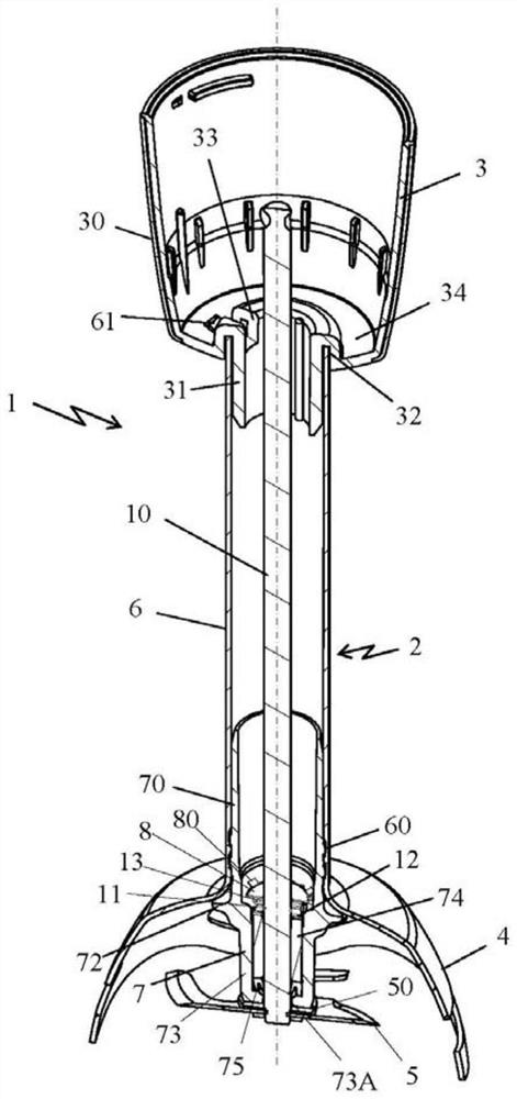
[0030] figure 1 A domestic blender is shown comprising a housing 100 containing an electric motor 101 schematically shown by dashed lines and arranged along the longitudinal axis X of the housing, the electric motor 101 having an output shaft at Its lower end is equipped with a rotary driver 102 protruding to the outside of the housing 100 .

[0031] The domestic agitator comprises a stirring foot 1 comprising a tubular cylinder 2 comprising an upper end integral with a flange 3 which allows stirring in one po...


PUM


Abstract

The invention relates to a stirring foot (1) comprising a connecting flange (3) and comprising a shaft (2), said connecting flange (3) allowing said stirring foot to be mounted detachably On the motor housing, the column shaft (2) contains a drive shaft (10), the drive shaft (10) includes an upper end and a lower end, the upper end is used to be driven to rotate by the motor housing, and The tool (5) is fixed on the lower end, and the flange (3) is connected to the upper end of the column (2) by fitting and assembling, and is characterized in that In that, the shaft (2) comprises a metal body (6) comprising at least one fixing tongue (61) bent against the A flange (3) in order to improve the pull-out resistance of said flange (3) relative to said shaft (2).

Description

technical field [0001] The present invention relates to the general technical field of domestic mixers of the extended type, and in particular to a mixing foot for grinding ingredients immersed in a liquid. Background technique [0002] Such stirring feet are well known and frequently used. The stirring foot is often detachably connected to a housing containing a motor, and the stirring foot includes a stirring tool integrated with a shaft, the upper end of which is connected to the output shaft of the motor. The high-speed driven tool penetrates into the interior of the food to be prepared, and cuts, mixes, emulsifies, and the like. [0003] Known document CN202341837U discloses a stirring foot, the stirring foot includes a connecting flange, the connecting flange allows the stirring foot to be detachably mounted on the electric housing, and the stirring foot includes a connecting flange connected to the flange. An integral column body, the column body includes a drive sh...

Claims


Application Information

Patent Timeline
Patent Type & Authority Patents(China)
IPC IPC(8): A47J43/07A47J43/08A47J43/044
CPCA47J43/044A47J43/0711A47J43/082A47J2043/04427
Inventor 弗兰克·阿姆兰斯特凡·格拉锡阿尔诺·维特尔
Owner SEB SA
Learn More