Needle holder for minimally invasive surgery

A technology of minimally invasive surgery and needle holders, applied in the field of medical equipment, can solve the problems of not using surgery, difficult inside the human body, large movements, etc., and achieve the effects of wide application prospects, improved oxidation resistance, and excellent electrical conductivity performance

Active Publication Date: 2018-10-30
江苏盐综产业投资发展有限公司
View PDF8 Cites 0 Cited by
  • Summary
  • Abstract
  • Description
  • Claims
  • Application Information

AI Technical Summary

Problems solved by technology

However, on the one hand, this limits the length of the needle holder, making it difficult to penetrate into the human body, especially in minimally invasive surgery.

Method used


Image

  • Needle holder for minimally invasive surgery
  • Needle holder for minimally invasive surgery

Examples


specific Embodiment 1

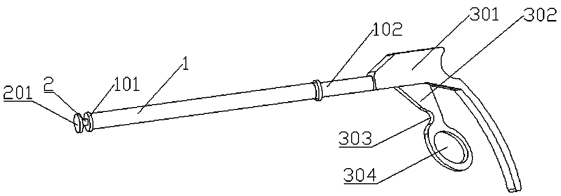
[0021] Specific embodiment 1: A needle holder for minimally invasive surgery, including:

[0022] The gun handle, the gun handle is located at the proximal end of the needle holder for operating the needle holder, and the gun handle includes a trigger 302;

[0023] Needle holder needle, the needle holder needle is used to hold the surgical needle, the needle holder needle includes a first clamping part 101 and a second clamping part 201;

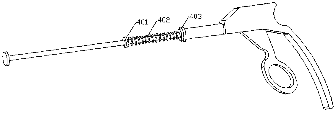
[0024] The connecting shaft is located between the gun handle and the needle of the needle holder, and is used for the gun handle to control the needle of the needle holder. The connecting shaft includes a hollow outer tube 1 and a pull rod 2, through which the pull rod 2 passes In the hollow position of the outer tube, the outer tube and the handle are fixedly connected, the trigger control pull rod moves along the axial direction of the outer tube, the first clamping part is connected with the pull rod, and the second clamping part is connected w...

specific Embodiment 2

[0027] Specific embodiment 2: The present invention discloses a preparation method of titanium alloy material: preparation according to the following steps:

[0028] Step 1. Select titanium raw materials and put them in the furnace;

[0029] Step two, turn on the power supply, pass in argon gas, maintain a vacuum of 15Kpa-40Kpa, preferably 20Kpa, heat to 1700°C-1800°C for melting, adjust the power appropriately according to the melt change to make the bubbles stable;

[0030] Step 3. When no bubbles are formed, blow in argon gas and maintain a vacuum of 50 Kpa -100 Kpa. At this time, add alloying elements, which are 100 parts titanium, 0.04 parts lithium, 0.03 parts zinc, and 0.04 parts chromium. , 0.02 parts of lanthanum and 0.02 parts of cerium.

[0031] Step 4: After melting for 10min-50min, cool down. When cooling, use ultrasonic irradiation to crystallize. Ultrasonic power is M*40W. M is the mass of molten alloy, and the unit is KG. Ultrasonic irradiation can increase the titaniu...


PUM


Abstract

The invention discloses a minimally invasive surgery needle holder, and belongs to the field of medical instruments. The minimally invasive surgery needle holder is used for clinical medical treatment, and aims to solve the problem about a needle holder in minimally invasive surgery. The needle holder comprises a gun handle, a needle holder needle and a connection shaft, wherein the gun handle is located at the near end of the needle holder and used for operating the needle holder; the gun handle comprises a trigger (302); the needle holder needle is used for clamping a surgical needle, the needle holder needle comprises a first clamping part (101) and a second clamping part (201), and the first clamping part and the second clamping part are made of titanium alloy materials; the connection shaft is located between the gun handle and the needle holder needle and used for the gun handle to control the needle holder needle; the connection shaft comprises a hollow outer tube (1) and a pull rod (2), the pull rod (2) penetrates through the hollow position of the outer tube, the outer tube is fixedly connected with the gun handle, the trigger controls the pull rod to move in the axial direction of the outer tube, the first clamping part is connected with the pull rod, and the second clamping part is connected with the outer tube.

Description

Technical field [0001] The present invention is in the field of medical equipment, specifically a needle holder. Background technique [0002] Needle holders are important and commonly used medical supplies, especially in surgery, they are often used. Existing needle holders are usually similar to scissors devices. The head is clamped and clamped by the principle of scissors lever. However, on the one hand, this limits the length of the needle holder, which makes it difficult to penetrate into the human body, especially in minimally invasive surgery. On the other hand, the design of the scissors results in a large amount of manual operation and does not use the operation to proceed. Summary of the invention [0003] In view of the above-mentioned problems, the present invention provides a minimally invasive surgical needle holder, including: [0004] The gun handle is located at the proximal end of the needle holder and is used to operate the needle holder. The gun handle includes ...

Claims


Application Information

Patent Timeline
Patent Type & Authority Patents(China)
IPC IPC(8): A61B17/062C22C14/00C22C1/02A61B17/00
CPCA61B17/00234A61B17/062A61B2017/00526C22C1/02C22C14/00
Inventor 王霞
Owner 江苏盐综产业投资发展有限公司
Why Eureka
Try Eureka