Detachable orthodontic bracket

An orthodontic bracket and bracket technology, applied in the field of orthodontics, can solve problems such as poor controllability of tooth movement, inability to accurately control the direction and amount of tooth movement, and poor movement in three-dimensional directions, so as to facilitate clinical operations and reduce chair-side problems. Operation time and the effect of reducing work intensity

Inactive Publication Date: 2017-09-19
常州宁新医疗科技有限公司
View PDF0 Cites 7 Cited by
  • Summary
  • Abstract
  • Description
  • Claims
  • Application Information

AI Technical Summary

Problems solved by technology

This orthodontic system has the following problems: 1. The controllability of tooth movement in the early alignment process is poor, mainly because in the orthodontic process at this stage, the movement of the teeth mainly depends on the free sliding of the archwire within the range of the bracket. It is impossible to precisely control the movement direction and amount of the teeth, which easily leads to unpredictable tooth movements; 2. In the later fine adjustment process, the square archwire and the square groove cannot achieve close contact, and there is a certain gap between the archwire and the groove. If there is a gap, the bracket needs to be pre-set with an additional angle or an additional torque is added to the arch wire to make some compensation.
However, the orthodontic system still has the following problems: 1. The lingual fixed appliance still uses the sliding principle of the labial fixed orthodontic and the interaction between the square arch wire and the bracket to realize the three-dimensional direction control of the teeth, so there is also the above-mentioned labial The problem of fixed orthodontic treatment, and the lingual bracket is smaller than the labial bracket, the groove is narrower, and the movement in the three-dimensional direction is worse; 2. At the same time, the lingual space is small, and the patient's mouth opening is limited. Interfilament ligation is more complex than labial and thus requires more specialized training and chair time for the clinician
The orthodontic system based on the sliding mechanism of the arch wire is difficult to achieve precise control of the amount and mode of tooth movement

Method used


Image

  • Detachable orthodontic bracket
  • Detachable orthodontic bracket
  • Detachable orthodontic bracket

Examples


Embodiment 1

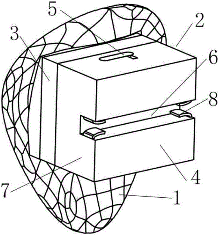
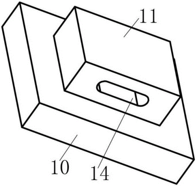
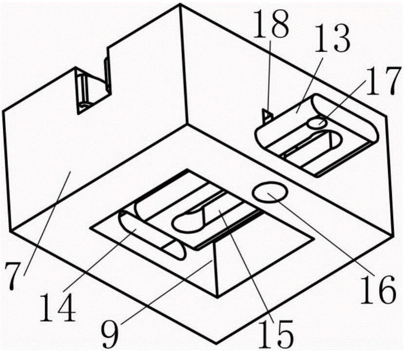
[0044] Embodiment 1: a kind of detachable orthodontic bracket, its structure diagram is as follows Figure 1-4 As shown, specifically, the boss portion of the bracket retainer is a cuboid lingual orthodontic bracket, including a bracket bottom plate 1 and a bracket body 2 . The bracket body 2 includes a bracket retainer 3 , a bracket movable body 4 , and a sliding pin-key connection structure 5 arranged on the bracket movable body 4 . Wherein the bracket movable body 4 is provided with an archwire groove 6 and a cuboid stopper 7; two pairs of elastic pieces 8 are arranged at both ends of the archwire groove 6; a cuboid-shaped opening is provided on the cuboid stopper 7 Cavity 9. Wherein the bracket retainer 3 is a boss structure, including a cuboid base part 10 connected to the bracket base plate 1 and a cuboid boss part 11 contained by the opening cavity 9, and the length and width of the cuboid base part 10 are larger than the cuboid boss Corresponding dimensions of part 1...

Embodiment 2

[0048] Embodiment 2: a kind of detachable orthodontic bracket, its structure diagram is as follows Figure 5-7 As shown, specifically, the boss part of the bracket retainer is a detachable orthodontic bracket with a cylinder combined with a cuboid, including a bracket bottom plate 19 and a bracket body. Wherein the bracket body includes a bracket retainer, a bracket movable body and a fitted engagement structure 20 arranged at the corresponding contact position of the bracket retainer and the bracket movable body. Both the bracket bottom plate 19 and the bracket body are standard parts, and the bracket bottom plate 19 and the bracket retainer are integrally formed. The bracket retainer is provided with a boss part 21 connected with the bracket movable body, which is a combination of a cuboid and a cylinder; the base part of the bracket retainer is a cuboid. The movable body of the bracket is provided with an archwire groove, a cuboid stopper, and two pairs of elastic plates a...

Embodiment 3

[0049] Embodiment 3: a bracket body of a detachable orthodontic bracket, its structural schematic diagram is as follows Figure 8-10 As shown, the boss part is a trapezoid. The bracket body includes a bracket retainer, a bracket movable body and a pin connection structure 25 . The bracket retainer includes a trapezoidal body base portion 26, a trapezoidal body boss portion 27, the size of the trapezoidal body boss portion 27 is smaller than the trapezoidal body base portion 26, and a thin layer of soft buffer is attached to the side wall of the trapezoidal body boss portion 27 Layer 28. The movable body of the bracket is provided with an archwire groove, a trapezoidal body stopper 29, and rigid clamping members 30 arranged at both ends of the archwire groove. An opening cavity 31 is arranged on the trapezoidal body limiting member, and its internal shape and size are set according to the trapezoidal body boss portion 27 . The opening cavity 31 is a transition fit with the t...


PUM


Abstract

The invention discloses a removable orthodontic bracket, which belongs to the technical field of tooth correction. The detachable orthodontic bracket includes a bracket bottom plate and a bracket body, and the bracket body includes a bracket retainer, a bracket movable body and a connecting member, and the bracket retainer is connected with the bracket retainer. The bracket bottom plate is connected, the bracket movable body is connected with the arch wire, the bracket retainer and the bracket movable body can be detachably connected through the connecting member, and the bracket movable body is provided with a can accommodate all or Open cavity for some bracket retainers. The orthodontic bracket can accurately transmit the deformation of the prefabricated archwire to the teeth, so that the movement mode and the movement amount of the teeth can be precisely controlled.

Description

technical field [0001] The invention relates to the technical field of orthodontics, in particular to an orthodontic bracket. Background technique [0002] Orthodontics is a discipline that treats misaligned teeth and tooth surface deformities through the application of orthodontic devices. At present, the most widely used bracket correction mainly includes fixed labial correction and customized lingual correction. [0003] Fixed labial correction is realized based on the interaction between the brackets bonded to the labial side and the sequence of arch wires, mainly including winged brackets (such as patent documents CN204446157U, CN2614644Y, CN202020559U), self-locking brackets (such as Patent documents CN104434324A, CN204636588U, CN201578387U), etc., in the early stage, the elasticity of the circular arch wire and the restriction of the orthodontic bracket to the arch wire were used to realize the teeth to slide freely according to the shape of the arch wire to achieve ...

Claims


Application Information

Patent Timeline
Patent Type & Authority Applications(China)
IPC IPC(8): A61C7/14A61C7/28
CPCA61C7/14A61C7/28
Inventor 赵宁钮叶新
Owner 常州宁新医疗科技有限公司
Why Eureka
Try Eureka