
Width Control Method of Wedge Blank Based on Fixed Width Side Press

A technology of width control and side pressing machine, which is applied in rolling mill control devices, manufacturing tools, metal rolling, etc., to achieve the effects of reducing width fluctuations, improving stability and yield, and large reduction capacity

Active Publication Date: 2019-10-25
BAOSHAN IRON & STEEL CO LTD
View PDF8 Cites 0 Cited by
  • Summary
  • Abstract
  • Description
  • Claims
  • Application Information

AI Technical Summary

Problems solved by technology

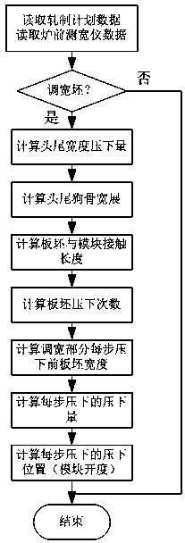
[0006] The technical problem to be solved by the present invention is to provide a method for controlling the width of a wedge-shaped billet based on a fixed-width side press, which solves the problem of controlling the width of a wedge-shaped billet whose head-to-tail width difference exceeds 100mm in hot continuous rolling production. The position information and the confirmation of the slab shape measured by the width measuring instrument in front of the furnace, using the characteristics of large reduction capacity and controllable step length of the fixed-width side press, combined with the target width of the rough rolling exit of the slab and the width after side pressing, Calculate the reduction and side pressure roll gap for the head and tail of the wedge-shaped blank and the width-adjusting part, and calculate the step length according to the width change rate of the width-adjusting part, so as to achieve precise control of the width of the wedge-shaped blank

Method used


Image

  • Width Control Method of Wedge Blank Based on Fixed Width Side Press
  • Width Control Method of Wedge Blank Based on Fixed Width Side Press
  • Width Control Method of Wedge Blank Based on Fixed Width Side Press

Examples


Embodiment 1

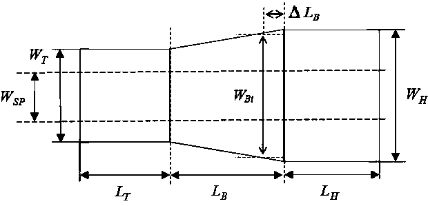
[0068] Such as image 3 As shown, a wedge-shaped blank width control method based on a fixed-width side press machine takes the slab with unequal head and tail width as the wedge-shaped blank, and sets the target width of the slab to be processed; the shape of the wedge-shaped blank to be processed is as follows figure 2 shown, where W H is the width of the equal width section of the head, W T is the width of the equal-width segment at the tail, W SP is the target width, L H is the length of the equal width section of the head, L T is the length of equal width segment at the tail, L B It is the length of the width adjustment section in the middle; the size parameters of the above-mentioned wedge-shaped billet are issued by the host computer or measured by the width measuring instrument in front of the furnace;

[0069] After the slab to be processed is determined to be a wedge-shaped slab from the obtained slab size parameters, follow the steps below:

[0070] S1: Divid...


PUM


Abstract

The invention relates to the field of steel rolling automatic control, in particular to a control method for a wedge-shaped base width. According to the control method for the wedge-shaped base width based on the fixed-width side pressure machine, a wedge-shaped base is divided into three sections based on a width change rule, the dog-bone broad-sidings of a head equal-width section and a tail equal-width section are respectively calculated to be used for correcting the rolling reduction, then the stepped number and the stepped size are calculated and obtained according to the rolling reduction after correction, and finally, each stepped rolling reduction of a widened section is calculated and obtained through inserting a value. According to the positional information of the wedge-shaped base width included in a rolling schedule issued by an upper computer and the slab actual shape actually measured by a stokehole width gauge, combined with the conditions of the flapping module shape of the fixed-width side pressure machine, the running speed of a roller bed and the like, by adopting gradually progressive and variable-rolling-reduction and variable-step-size control methods, the uniformity of the width of the total length of the wedge-shaped base which is rolled by the fixed-width side pressure machine is ensured, the width fluctuation of the total length of the wedge-shaped base is effectively reduced, and the rolling stability and the finishing product rate are improved.

Description

technical field [0001] The invention relates to the field of automatic control of steel rolling, in particular to a method for controlling the width of a wedge-shaped billet. Background technique [0002] The wedge-shaped billet is the transitional billet produced when the width of the mold is adjusted during the continuous casting process. This kind of wedge-shaped billet cannot be set and controlled automatically by relying on the existing hot-rolling automation technology and control model, so some control models need to be specially designed. [0003] Chinese patent CN201210211053.9 discloses a hot-rolled width control method for wedge-shaped slabs, which mainly discloses a hot-rolled width control method for wedge-shaped slabs, which is used for hot-rolling wedge-shaped slabs The hot-rolled width is controlled, and the method comprises the steps of: (1) determining whether the incoming slab is a wedge-shaped slab according to the head-to-tail width difference of the in...

Claims


Application Information

Patent Timeline
Patent Type & Authority Patents(China)
IPC IPC(8): B21B37/22
CPCB21B37/22B21B2261/06
Inventor 侯悦朱健勤董晖李庆邵志强吴真权刘苗
Owner BAOSHAN IRON & STEEL CO LTD
Learn More