Effectively fix the structure of the fuel cell stack

A fuel cell stack and support plate technology, which is applied to battery pack components, structural parts, circuits, etc., can solve problems such as unstable performance of fuel cell stacks, hydrogen leakage, and performance degradation of stacks, so as to increase service life and ensure safety Reliability, safe and reliable use, and long service life

Active Publication Date: 2020-09-04
山东汉德自动化控制设备有限公司
View PDF8 Cites 0 Cited by
  • Summary
  • Abstract
  • Description
  • Claims
  • Application Information

AI Technical Summary

Problems solved by technology

[0007] The technical problem to be solved by the present invention is that when the UAV is in use, it is easy to shake and easily lead to instability of the performance of each single cell of the fuel cell stack. However, in the existing bolt fixing mode, the vibration will easily cause the nuts of the bolts to loosen. The contact resistance of the electric stack increases, resulting in a decrease in the performance of the electric stack and a reduction in the life of the electric stack. In severe cases, the electric stack leaks, and an explosion may occur due to hydrogen leakage.
The purpose is to provide a structure for effectively fixing the fuel cell stack and solve the problem of fixed installation of the fuel cell

Method used


Image

  • Effectively fix the structure of the fuel cell stack
  • Effectively fix the structure of the fuel cell stack

Examples


Embodiment 1

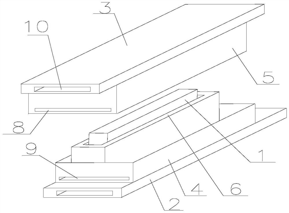
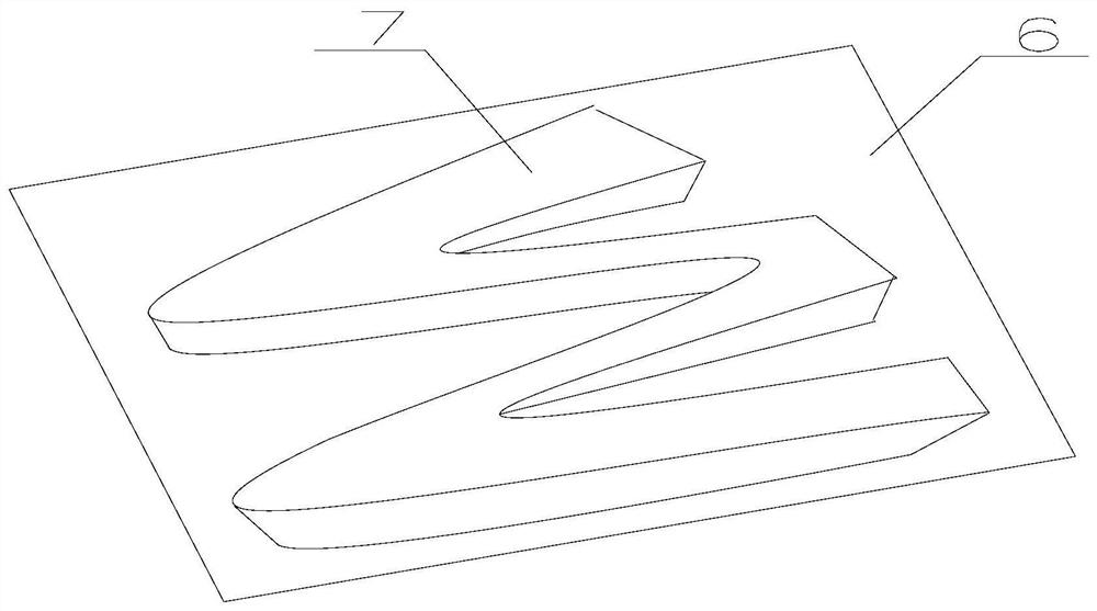
[0028] Such as figure 1 and figure 2 As shown, the structure of the present invention to effectively fix the fuel cell stack includes a fuel cell stack 1, a lower support plate 2 and an upper support plate 3 for fixing the fuel cell stack 1, and the lower support plate 2 and the upper support plate 3 are both There is a groove A for placing the fuel cell stack 1, the lower support plate 2 is connected with a placement groove 4 surrounding the fuel cell stack 1, and there is a buffer plate 6 between the placement groove 4 and the fuel cell stack 1 , the buffer plate 6 includes a pressure dispersion plate and a wave-shaped elastic buffer plate 7 located on the pressure dispersion plate, the buffer plate 7 is in contact with the side of the fuel cell stack 1, and there are several small holes on the buffer plate 7 hole, the upper support plate 3 has a groove B for clamping the buffer plate 6, and the upper support plate 3 is connected with a connecting plate 5 set in the placem...

Embodiment 2

[0030] The structure for effectively fixing the fuel cell stack includes a fuel cell stack 1, a lower support plate 2 and an upper support plate 3 for fixing the fuel cell stack 1, and the lower support plate 2 and the upper support plate 3 are provided with The groove A for placing the fuel cell stack 1, the lower support plate 2 is connected with a placement groove 4 surrounding the fuel cell stack 1, and there is a buffer plate 6 between the placement groove 4 and the fuel cell stack 1, so The buffer plate 6 includes a pressure dispersion plate and a wave-shaped elastic buffer plate 7 located on the pressure dispersion plate. The buffer plate 7 is in contact with the side of the fuel cell stack 1. There are a number of small through holes on the buffer plate 7. The upper support plate 3 has a groove B for clamping the buffer plate 6, and the upper support plate 3 is connected with a connection plate 5 set in the placement groove 4. When the connection plate 5 is set in the p...

Embodiment 3

[0032] The structure for effectively fixing the fuel cell stack includes a fuel cell stack 1, a lower support plate 2 and an upper support plate 3 for fixing the fuel cell stack 1, and the lower support plate 2 and the upper support plate 3 are provided with The groove A for placing the fuel cell stack 1, the lower support plate 2 is connected with a placement groove 4 surrounding the fuel cell stack 1, and there is a buffer plate 6 between the placement groove 4 and the fuel cell stack 1, so The buffer plate 6 includes a pressure dispersion plate and a wave-shaped elastic buffer plate 7 located on the pressure dispersion plate. The buffer plate 7 is in contact with the side of the fuel cell stack 1. There are a number of small through holes on the buffer plate 7. The upper support plate 3 has a groove B for clamping the buffer plate 6, and the upper support plate 3 is connected with a connection plate 5 set in the placement groove 4. When the connection plate 5 is set in the p...


PUM


Abstract

The invention discloses a structure for effectively fixing a fuel cell unit. The structure comprises the fuel cell unit, a lower supporting plate and an upper supporting plate, wherein the lower supporting plate and the upper supporting plate are used for fixing the fuel cell unit. Grooves A for placing the fuel cell unit are formed in the lower supporting plate and the upper supporting plate, a storage slot for surrounding the fuel cell unit inside is connected onto the lower supporting plate, a buffer plate is arranged between the storage slot and the fuel cell unit and comprises a pressure dispersion plate and a wavy elastic buffer plate positioned on the pressure dispersion plate, the buffer plate contacts with the side face of the fuel cell unit, a plurality of small through holes are formed in the buffer plate, a groove B for clamping the buffer plate is formed in the upper supporting plate, a connecting plate is connected onto the upper supporting plate, the storage slot internally sleeves the connecting plate, and the fuel cell unit and the buffer plate are positioned on the grooves A and the groove B when the storage slot internally sleeves the connecting plate.

Description

technical field [0001] The invention relates to a fuel cell, in particular to a structure for effectively fixing a fuel cell group. Background technique [0002] With the development of fuel cell technology, its application fields are becoming wider and wider. At present, some types of drones use fuel cell packs to power motors and other electronic devices. However, after the fuel cell is installed in the drone, its fixing problem has not been paid attention to. Since the fuel cell has not been well fixed, it is very easy to have subtle vibrations during take-off, landing and aerial photography. Over time , it will further cause the instability of the performance of each single cell of the fuel cell stack. [0003] Moreover, fuel cells are more and more popular and used by people because of their advantages such as high energy conversion efficiency, low noise, low carbon, zero emissions, flexible and convenient use, low operating temperature, and high energy density. Fuel ...

Claims


Application Information

Patent Timeline
Patent Type & Authority Patents(China)
IPC IPC(8): H01M2/10
CPCH01M50/20Y02E60/10
Inventor 李廷帅黄蹬峰杨鸣
Owner 山东汉德自动化控制设备有限公司
Why Eureka
Try Eureka