A steel pipe punching and shearing machine

A technology for punching and shearing machines and steel pipes, which is applied in the field of processing steel pipe punching and shearing machines and ends of steel pipes. It can solve the problems of difficult control of the pairing gap, poor cutting surface quality, and low construction efficiency, and achieve excellent forming and high processing efficiency. , The effect of low processing cost

Active Publication Date: 2019-07-30
SEPCO ELECTRIC POWER CONSTR CORP
View PDF5 Cites 0 Cited by
  • Summary
  • Abstract
  • Description
  • Claims
  • Application Information

AI Technical Summary

Problems solved by technology

[0003] The object of the present invention is to provide a steel pipe punching and shearing machine, which overcomes the low precision of the existing method, poor cutting surface quality, large and uneven weld seam gap, difficult control of the gap between groups, poor process quality and poor construction The problem of inefficiency

Method used


Image

  • A steel pipe punching and shearing machine
  • A steel pipe punching and shearing machine
  • A steel pipe punching and shearing machine

Examples


Embodiment 1

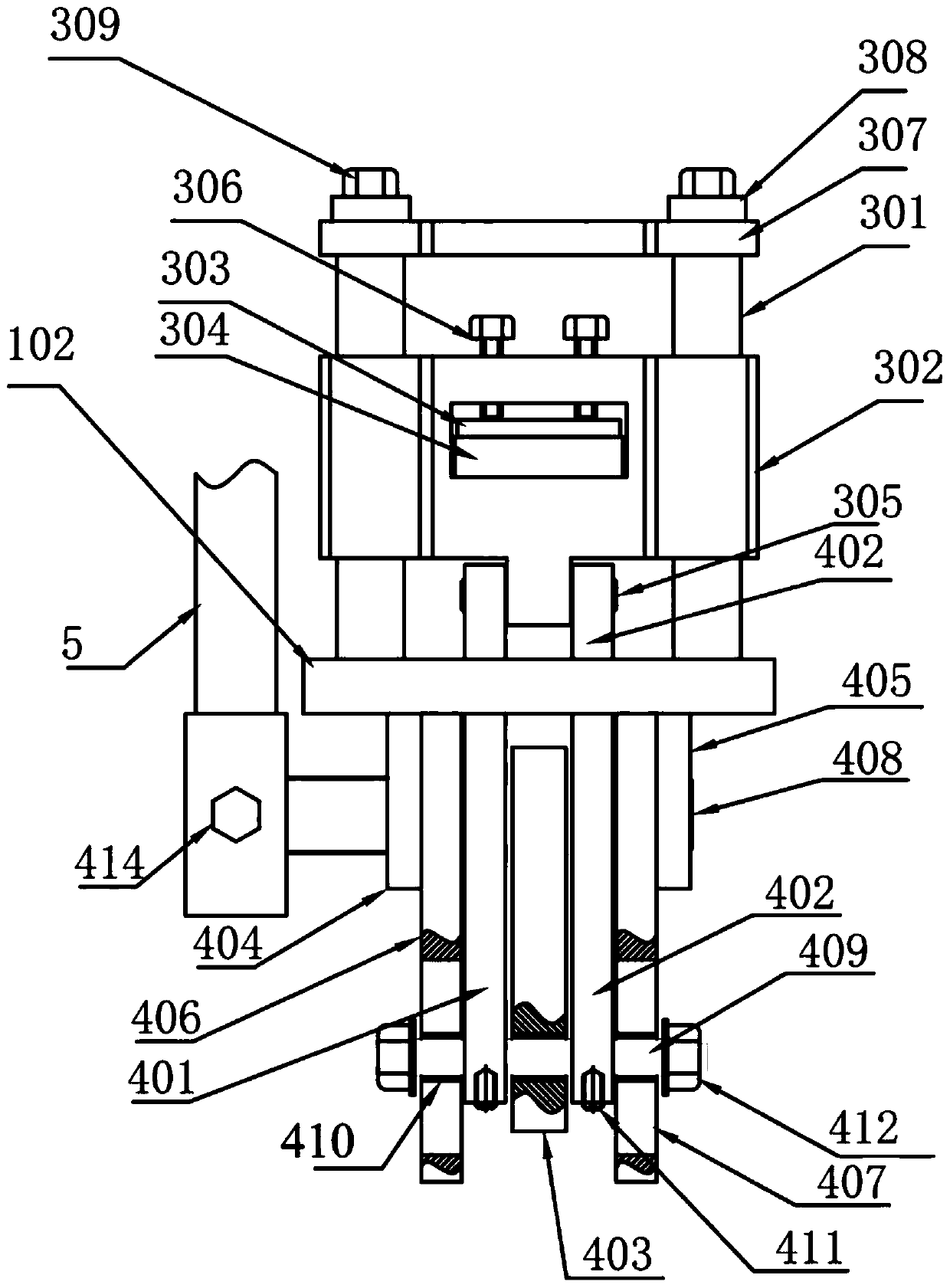
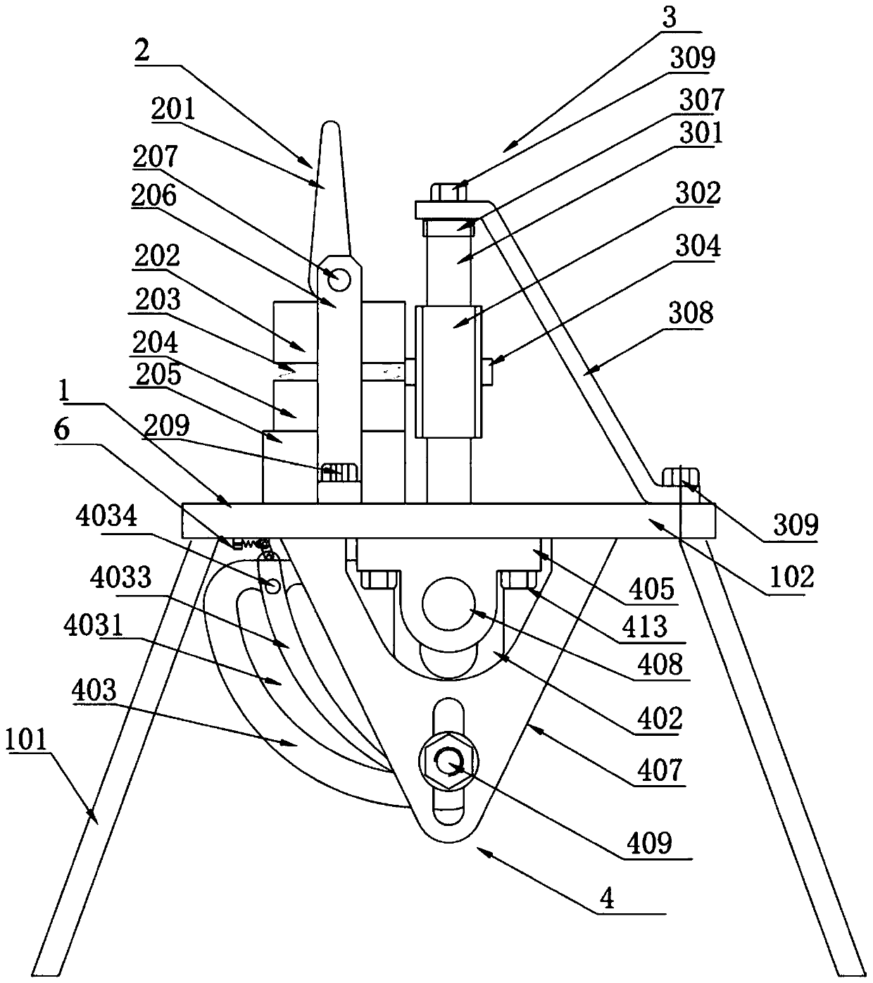
[0086] Such as figure 1 , figure 2 with image 3 As shown, a steel pipe punching and shearing machine includes a bracket auxiliary system 1, a locking device 2, a tool holder device 3, a transmission device 4, and a pressing rod 5. The bracket auxiliary system 1 includes a leg 101 and a base plate 102, There are four legs 101, located below the base plate 102, fixedly connected with the four corners of the bottom of the base plate 102; The upper plane of the seat plate 102 is fixedly connected; the transmission device 4 is located below the base plate, and is fixedly connected with the lower plane of the base plate 102;

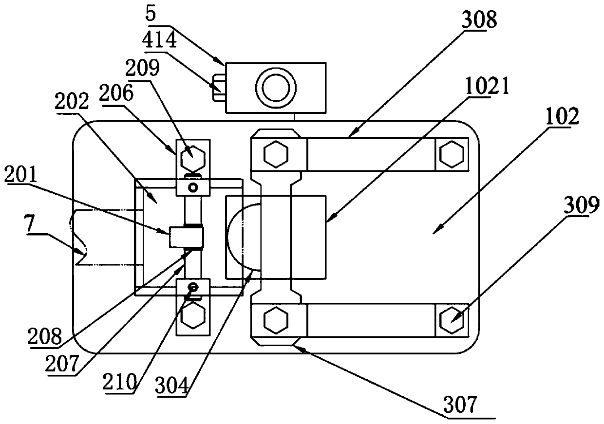
[0087] Such as Figure 4 As shown, a base plate hole 1021 is opened in the middle of the base plate 102, and the transmission device 4 passes through the hole to connect with the tool rest device 3 directly above, and the feature is that the pipe fitting 7 is placed in the The punching position of the adjacent knife rest device 3 drives the transmission ...

Embodiment 2

[0119] On the basis of Embodiment 1, the first fixed shaft 6014 of the puller is in an "L" shape, the top is fixedly mounted on the bottom of the base plate 102, and the bottom is connected with the first fixed hole 60131 of the puller for rotation; the second fixed shaft 6024 of the puller is connected to the The fixed shaft 6014 of the first part is the same and is also in the shape of "L".

[0120] A steel pipe punching and shearing machine of the present invention operates as follows:

[0121] 1. Select the upper die 202 and lower die 204 of the corresponding type according to the pipe diameter of the pipe fitting 7, and install them on the locking device 2 of the steel pipe punching and shearing machine;

[0122] 2. Select the corresponding type of punching head 304 according to the pipe diameter of the pipe fitting 7, and install it in the sliding knife holder 302 of the steel pipe punching and shearing machine;

[0123] 3. Insert the end of the pipe fitting 7 into the ...


PUM


Abstract

The invention relates to a steel pipe punching and shearing machine which is particularly suitable for machining the end parts of steel pipes in T-shaped connectors of steel pipe railings of ladder platforms for electric power and constructional engineering construction, and belongs to the technical field of mechanical equipment. The steel pipe punching and shearing machine comprises a support auxiliary system (1), a locking device (2), a knife rest device (3), a transmission device (4) and a pressure rod (5) and can shear the side pipe wall of a pipe (7); as an improvement, the steel pipe punching and shearing machine further comprises a shifting block device (6); a cam plate (403) is adjusted into an outer cam through a first shifting block device (601), the pressure rod (5) is pressed down so as to drive the cam plate (403) to rotate, and a transmission plate (401) and a transmission plate (402) are driven to move through a movable shaft (409) so as to drive a sliding knife rest (302) to move downwards to complete shearing of the pipe wall at the lower side of the pipe (7); and the pressure rod (5) is reset, the cam plate (403) is adjusted into an inner cam through a second shifting block device (602), the pressure rod (5) is pressed down, and the pipe wall on the upper side of the pipe (7) is sheared. According to the steel pipe punching and shearing machine, the punching and shearing operation of the end parts of the steel pipes with various pipe diameters can be completed, machining and forming can be realized at a time, and therefore the pairing efficiency and the welding quality of the T-shaped connectors of the steel pipe railings can be improved.

Description

technical field [0001] The invention belongs to the technical field of mechanical equipment, and in particular relates to a steel pipe punching and shearing machine, which is especially suitable for processing steel pipe ends in T-shaped joints of steel pipe railings on ladder platforms in electric power and construction projects. Background technique [0002] In the welding process of steel pipe components, such as the intersection of steel pipes, the method of flame cutting and blanking is often used for production. The precision of this method is not high, the cutting surface quality is poor, and the formed weld seam gap is large and uneven, which not only seriously affects the quality of the weld seam, but also easily leads to welding deformation of the steel pipe structural parts, making the external appearance of the welded steel pipe members The aesthetics and internal strength are not up to the requirements, which seriously affects the assembly quality of the product...

Claims


Application Information

Patent Timeline
Patent Type & Authority Patents(China)
IPC IPC(8): B21D28/02B21D28/04B21D28/20
CPCB21D28/02B21D28/04B21D28/20
Inventor 马刚王进刘立峰田野杜忠刘沅
Owner SEPCO ELECTRIC POWER CONSTR CORP
Why Eureka
Try Eureka