
Motion control method and device for mechanical arm, storage medium, and computer

A motion control and robotic arm technology, applied in the field of robotics, can solve problems such as reducing the motion control efficiency of the rotating axis of the robotic arm, and achieve the effect of improving the motion control efficiency

Active Publication Date: 2020-07-31
RIZHAO YUEJIANG TECH CO LTD
View PDF6 Cites 0 Cited by
  • Summary
  • Abstract
  • Description
  • Claims
  • Application Information

AI Technical Summary

Problems solved by technology

It can be seen that this motion control method mainly has the following defects: the user indirectly controls the manipulator through the application interface on the PC or mobile terminal, which reduces the user's motion control efficiency on the rotational axis of the manipulator to a certain extent.

Method used


Image

  • Motion control method and device for mechanical arm, storage medium, and computer
  • Motion control method and device for mechanical arm, storage medium, and computer
  • Motion control method and device for mechanical arm, storage medium, and computer

Examples


Embodiment Construction

[0033] Embodiments of the present invention provide a motion control method and device for a mechanical arm, a storage medium, and a computer, which are used to solve the problem that the interface buttons in the application interface cannot intuitively correspond to the rotation direction of the rotational axis of the mechanical arm.

[0034] In order to make the purpose, features and advantages of the present invention more obvious and understandable, the technical solutions in the embodiments of the present invention will be clearly and completely described below in conjunction with the accompanying drawings in the embodiments of the present invention. Obviously, the following The described embodiments are only some, not all, embodiments of the present invention. Based on the embodiments of the present invention, all other embodiments obtained by persons of ordinary skill in the art without making creative efforts belong to the protection scope of the present invention.

[...


PUM


Abstract

The embodiment of the invention discloses a motion controlling method for a mechanical arm. The method is used for solving the problem that interface buttons of an application interface cannot intuitively correspond to the rotating direction of a rotating shaft of the mechanical arm. The method of the embodiment of the invention comprises the following steps that triggering events of a first triggering part and a second triggering part of controlling equipment are monitored; a first rotating control instruction is generated if a first triggering event of the first triggering part is monitored, and the first rotating control instruction is sent to the mechanical arm, so that an objective rotating shaft of the mechanical arm is driven according to the first rotating control instruction to rotate in a first rotating direction at a preset first rotating speed; a second rotating control instruction is generated if a second triggering event of the second triggering part is monitored, and the second rotating control instruction is sent to the mechanical arm, so that the objective rotating shaft is driven to rotate according to the second rotating control instruction; the first rotating direction is opposite to the second rotating direction. The embodiment of the invention further provides a motion controlling device for the mechanical arm, a storage medium and a computer.

Description

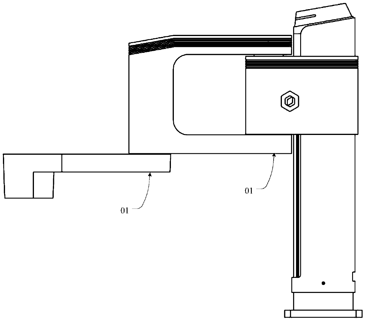
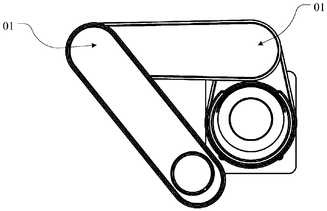
technical field [0001] The invention relates to the technical field of robots, in particular to a motion control method and device for a mechanical arm, a storage medium, and a computer. Background technique [0002] With the acceleration of industrial upgrading and technological progress of enterprises, the robotic arm has become an automated mechanical device that has been widely used in the field of robotics. This type of robotic arm has multiple degrees of freedom and allows movement in two-dimensional or three-dimensional space. Control instructions to complete various jobs. [0003] Such as Figure 1a , 1b , 1c and 1d, in order to improve the freedom of movement of the manipulator, the manipulator is often equipped with a rotating shaft, through which the manipulator can rotate around the rotating shaft within a certain range. In some special functions, the rotating The movement can greatly improve the working ability of the robotic arm. in, Figure 1a~1c The mecha...

Claims


Application Information

Patent Timeline
Patent Type & Authority Patents(China)
IPC IPC(8): G06F3/0338G06F9/30B25J9/16B25J13/00
CPCB25J9/161B25J9/1661B25J13/00G06F3/0338G06F9/30094
Inventor 刘培超刘主福
Owner RIZHAO YUEJIANG TECH CO LTD
Learn More