Cage door for mine hoisting

A technology of cages and mines, which is applied to lifting equipment, transportation and packaging in mines, can solve the problems of potential safety hazards, increase the number of operators, and hidden dangers of tankers, and achieve the effect of reducing human error

Active Publication Date: 2017-09-22
徐州市三森威尔矿山科技有限公司
View PDF5 Cites 2 Cited by
  • Summary
  • Abstract
  • Description
  • Claims
  • Application Information

AI Technical Summary

Problems solved by technology

[0003] The door curtain in the tank currently in use is just a simple door curtain welded with iron chains and steel pipes on the side of the cage entering and exiting the car. After the tank is stopped, it is lifted by hydraulic pressure or manually. The outer door curtain counterweight realizes the opening and closing of the tank door. This method requires the cage to run to a specific location at the wellhead to open the door beam, which is poor in practicability and has potential safety hazards. The manual lifting method affects the lifting efficiency and increases the workload of personnel. volume, increased number of workers
[0004] With the modernization of mine hoisting, the requirements for safety and efficiency continue to rise. In the case of a large number of people in the cage and high humidity in the shaft, the simple fence inside the tank can no longer meet the safety requirements of the tankers. Personnel bring safety hazards, how to ensure the safety of tankers, improve the environment of tankers, and improve transportation efficiency has become a major problem that needs to be solved urgently in cage transportation

Method used


Image

  • Cage door for mine hoisting
  • Cage door for mine hoisting
  • Cage door for mine hoisting

Examples


Embodiment Construction

[0022] The present invention will be further described below according to the accompanying drawings and embodiments.

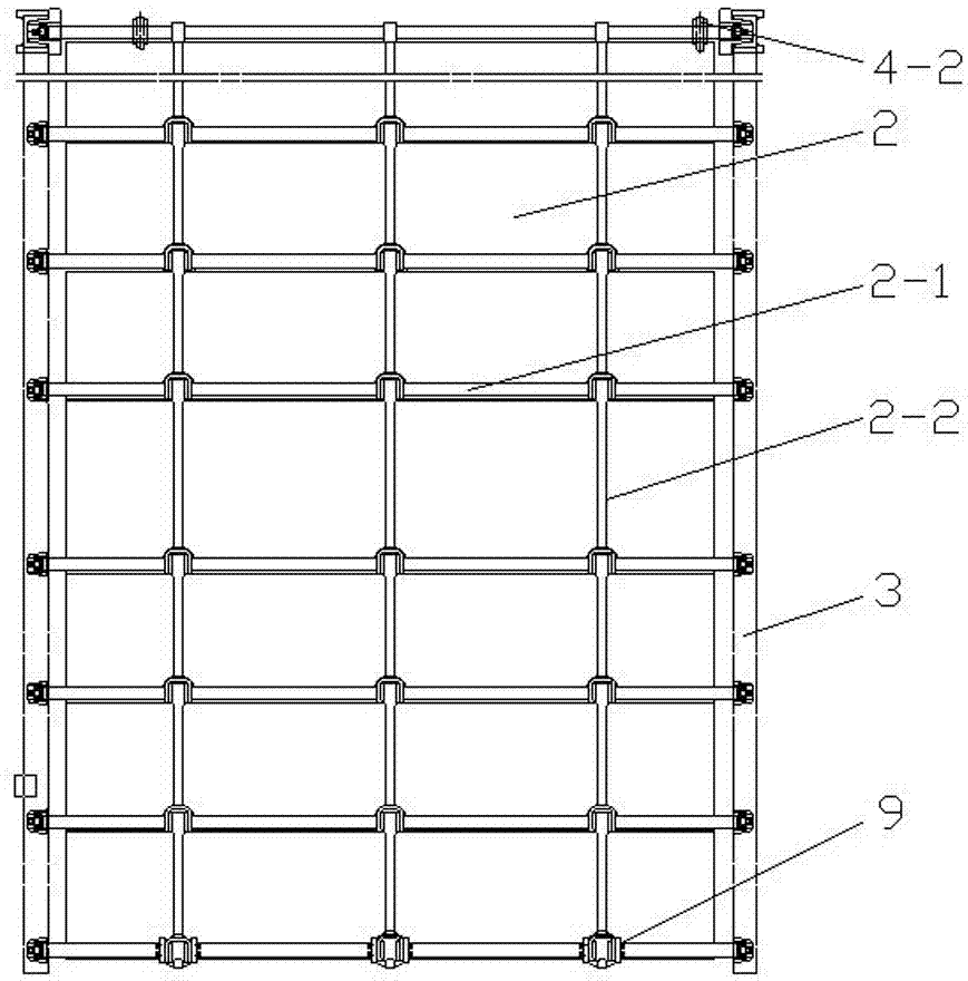
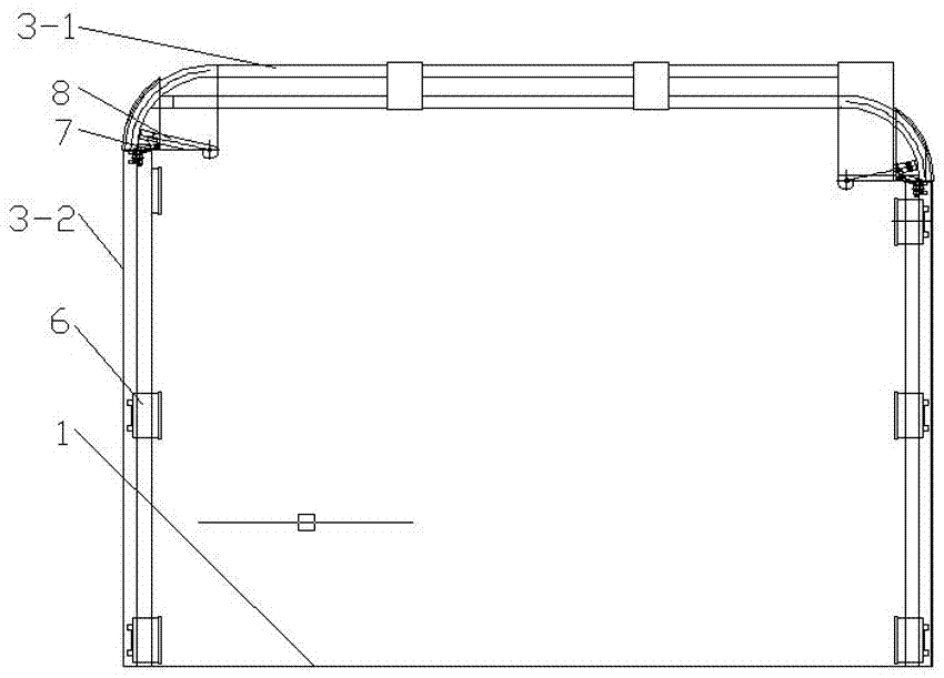
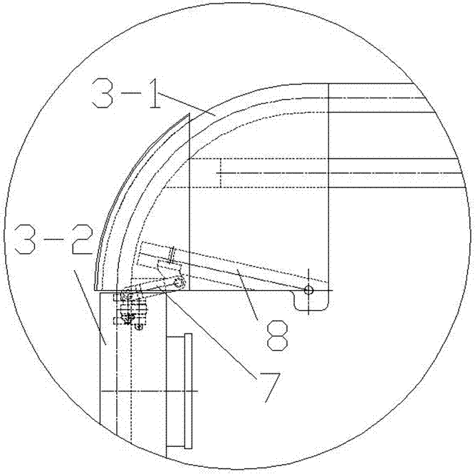
[0023] like Figure 1 to Figure 6 As shown, a cage door used for mine lifting is provided with a guide rail 3 for fixing the safety door 2 on the cage 1, and the guide rail 3 extends from the bottom of the opening side of the cage 1 to the top plane of the cage 1 so that the safety door 2 can be lifted from the cage. 1. The opening side is drawn to the top plane of the cage 1. The turning point of the guide rail 3 adopts a circular arc transition. The top plane of the cage 1 is provided with a transmission device 4 for driving the action of the safety door 2. The transmission device 4 is powered by the power device 5. The cage 1 has two front and rear openings, each opening is provided with a safety door 2, and the guide rails 3 on the front and rear opening sides of the cage 1 are arranged in a staggered manner at the top plane of the cage 1.

[0024] The sa...


PUM


Abstract

The invention belongs to the field of mine vertical shaft hoisting equipment, and particularly relates to a cage door for mine hoisting. Guide rails for fixing safety doors are arranged on a cage and extend to the flat surface of the top of the cage from the bottoms of the opening sides of the cage so as to enable the safety doors to be pulled to the flat surface of the top of the cage from the opening sides of the cage; the turnings of the guide rails are of circular arc transition structures; a transmission device for driving the safety doors to move is arranged on the flat surface of the top of the cage and is powered by a power device; a front opening and a rear opening are formed in the cage; each opening is provided with the safety door; and the guide rails of the front opening side and the rear opening side of the cage are staggered on the flat surface of the top of the cage. The cage doors are interlocked with a shaft mouth car handing system; and after the cage is in place, the cage doors automatically open, thereby reducing the errors of manual operation. The potential energy generated during the up and down movement of the cage is stored by a power accumulator in the cage door so as to provide energy sources for the power device. The cage door is energy-saving and environmentally-friendly; and meanwhile, a latticed frame structure is adopted, so that the sight line of a cage riding person is not blocked.

Description

technical field [0001] The invention belongs to the field of mine shaft hoisting equipment, and in particular relates to a cage door used for mine hoisting. Background technique [0002] In the vertical shaft hoisting mine, the cage is an important equipment for mine hoisting. In order to facilitate the entry and exit of mine cars, both sides of the cage are open structures. In order to prevent people from falling into the shaft during manned operation, door curtains are added on both sides of the tank. [0003] The door curtain in the tank currently in use is just a simple door curtain welded with iron chains and steel pipes on the side of the cage entering and exiting the car. After the tank is stopped, it is lifted by hydraulic pressure or manually. The outer door curtain counterweight realizes the opening and closing of the tank door. This method requires the cage to run to a specific location at the wellhead to open the door beam, which is poor in practicability and has...

Claims


Application Information

Patent Timeline
Patent Type & Authority Applications(China)
IPC IPC(8): B66B17/04B66B17/36
CPCB66B17/04B66B17/36Y02B50/00
Inventor 于拥军
Owner 徐州市三森威尔矿山科技有限公司
Why Eureka
Try Eureka