a diaphragm pump
A diaphragm pump and pump body technology, applied in the field of water flow interruption control components, can solve the problems of poor water sealing and large vibration at the water sealing port, and achieve the effects of low cost, reduced vibration, and guaranteed tightness.
- Summary
- Abstract
- Description
- Claims
- Application Information
AI Technical Summary
Problems solved by technology
Method used
Image
Examples
Embodiment 1
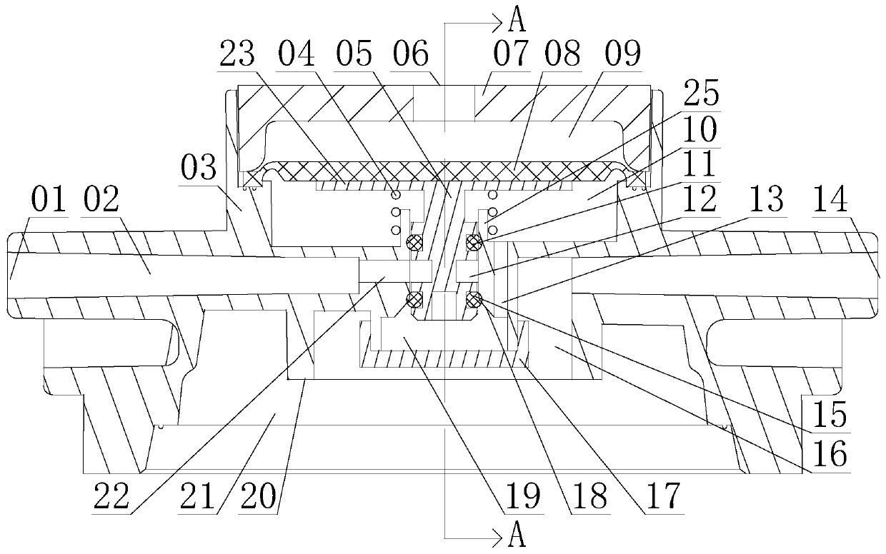
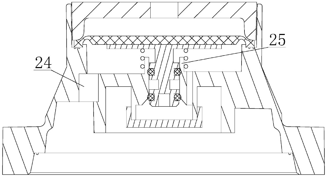
[0025] like figure 1 and figure 2As shown, a diaphragm pump includes a pump body and a water cut-off assembly arranged in the pump body, wherein the pump body includes a pump head body 03, an upper cover 07 and an inner gland-17, and the upper cover 07 is sealed with the top of the pump head body 03 It is connected with the pump head body 03 to form an accommodating cavity. The water cut-off component separates the accommodating cavity to form two upper and lower cavities. The lower cavity is the water passage cavity 10, and the upper cavity is the air pressure cavity 09 , The upper cover 07 forms a vent 06 connecting the air pressure chamber 09 with the outside world. The pump head body 03 of this embodiment is composed of a water inlet 01, a water outlet 14, a sealing sleeve 25, and a water inlet channel 02 and a water inlet channel that are sequentially arranged on the connection channel from the water inlet 01 to the water outlet 14. 22. The low-pressure chamber 21 and ...
Embodiment 2
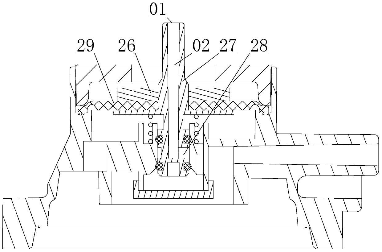
[0030] like image 3 As shown, the difference between this embodiment and embodiment 1 is: this embodiment uses control two 27 to replace the control rod one 05 in embodiment 1, and adopts air sealing diaphragm two 29 to replace the air sealing diaphragm one 08 in embodiment 1. The structure of the control rod 27 in this embodiment is different from that of the control rod 105. The top plate 23 is formed by the side wall of the control rod 27 protruding outward. Located outside the pump body. In this embodiment, the water inlet 01, water inlet channel 1 02, and water inlet channel 2 22 are not arranged on the pump head body 03, the water inlet 01 is arranged on the top of the control rod 27, the water inlet channel 1 02 and the water inlet channel 2 22 Also be arranged on the control rod two 27. The water inlet chamber in this embodiment is formed by the water inlet chamber 2 28 between the control rod 2 27 , the sealing ring 11 , the water sealing ring 15 , and the inner wa...
Embodiment 3
[0032] like Figure 4 As shown, the difference between this embodiment and Embodiment 1 is: this embodiment is not provided with the water passage two 19 described in Embodiment 1, and the control rod one 05 of this embodiment is formed with a water passage three 30, and the water passage three 30 is formed on the control rod one 05 of the present embodiment. The first water chamber 10 and the second water passage 19 are connected through the third water passage 30 , and the lower opening end of the first sealing sleeve 25 of this embodiment is arranged in the low-pressure chamber 21 .
PUM
 Abstract
Description
Claims
Application Information
 - R&D
- Intellectual Property
- Life Sciences
- Materials
- Tech Scout
- Unparalleled Data Quality
- Higher Quality Content
- 60% Fewer Hallucinations
Browse by: Latest US Patents, China's latest patents, Technical Efficacy Thesaurus, Application Domain, Technology Topic, Popular Technical Reports.
© 2025 PatSnap. All rights reserved.Legal|Privacy policy|Modern Slavery Act Transparency Statement|Sitemap|About US| Contact US: help@patsnap.com


