

Underwater seal device
A technology of sealing device and sealing ring, which is applied in the direction of engine sealing, engine components, mechanical equipment, etc., can solve the problems of increasing wear of parts, potential safety hazards, affecting product quality, etc., and achieve good dynamic sealing effect and prevent medium intrusion.
- Summary
- Abstract
- Description
- Claims
- Application Information
AI Technical Summary
Problems solved by technology
Method used
Image

Examples
Embodiment 1
[0024] The present invention provides an underwater sealing device, which includes a housing, a first end cover 7, a first sealing ring 8, a second end cover 6, and a second sealing ring 10.
[0025] The housing has an assembly cavity, and the first end cover 7 and the second end cover 6 are respectively connected to the two ends of the housing; the first end cover 7 has a first matching hole, and the first end cover 7 passes through the first sealing ring 8 It forms a dynamic seal with the matching piece 9 installed in the first matching hole. The second end cover 6 has a second matching hole, and the second end cover 6 forms a dynamic seal with the matching member 9 installed in the second matching hole through the second sealing ring 10.
[0026] The fitting 9 has at least a revolving part with an axis as a revolving shaft.
[0027] The housing has a first coupling flange and a second coupling flange, and both the first coupling flange and the second coupling flange have mounting...
Embodiment 2
[0031] The present invention provides an underwater sealing device, which includes a housing, a first end cover 7, a first sealing ring 8, a third end cover 3, a third sealing ring 5, and an emergency sealing gland 4.
[0032] The housing has an assembly cavity, the first end cover 7 and the third end cover 3 are respectively connected to the two ends of the housing; the first end cover 7 has a first matching hole, the first end cover 7 passes through the first sealing ring 8 It forms a dynamic seal with the matching piece 9 installed in the first matching hole. The third end cover 3 has a third matching hole, and the third end cover 3 forms a static seal with the matching member 9 installed in the third matching hole through the third sealing ring 5.
[0033] The emergency sealing gland 4 has an axially extending annular protrusion; the third end cover 3 has a receiving hole communicating with the third matching hole, the cross-sectional area of the receiving hole is larger than...
Embodiment 3
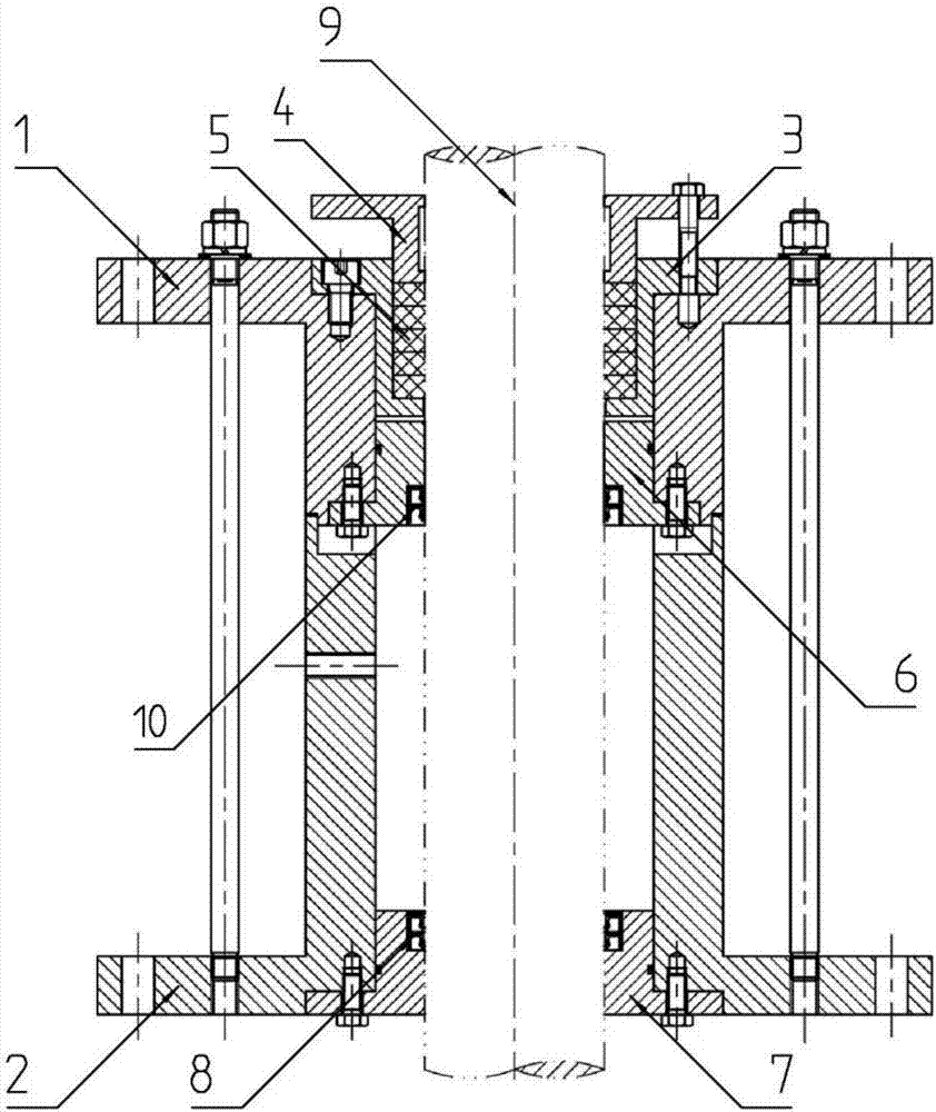
[0039] Such as figure 1 As shown, the present invention provides an underwater sealing device, including: a housing, a first end cover 7, a first sealing ring 8, a second end cover 6, a second sealing ring 10, a third end cover 3, and a third Sealing ring 5 and emergency sealing gland 4.
[0040] The housing has an assembly cavity. The first end cover 7, the second end cover 6 and the third end cover 3 are sequentially connected to the housing; the first end cover 7 has a first matching hole, and the first end cover 7 passes through the first The sealing ring 8 and the matching piece 9 installed in the first matching hole constitute a dynamic seal. The second end cover 6 has a second matching hole, and the second end cover 6 forms a dynamic seal with the matching member 9 installed in the second matching hole through the second sealing ring 10. The third end cover 3 has a third matching hole, and the third end cover 3 forms a static seal with the matching member 9 installed in ...
PUM
 Abstract
Description
Claims
Application Information