Vision calibration method and system, and unmanned aerial vehicle

A UAV and calibration technology, applied in the field of image recognition, can solve problems such as prone to errors, affecting the take-off of UAV, inconsistent orientation of UAV landing, etc., to reduce the frequency of occurrence, enrich geometric features, and improve accuracy Effect

Active Publication Date: 2017-09-22
GUANGDONG UNIV OF TECH
View PDF6 Cites 18 Cited by
  • Summary
  • Abstract
  • Description
  • Claims
  • Application Information

AI Technical Summary

Problems solved by technology

Because only the geometric feature of the existing square is recognized and detected, it is easy to make mistakes, and other patterns similar to concentric squares are included in the recognit...

Method used


Image

  • Vision calibration method and system, and unmanned aerial vehicle
  • Vision calibration method and system, and unmanned aerial vehicle
  • Vision calibration method and system, and unmanned aerial vehicle

Examples


Embodiment Construction

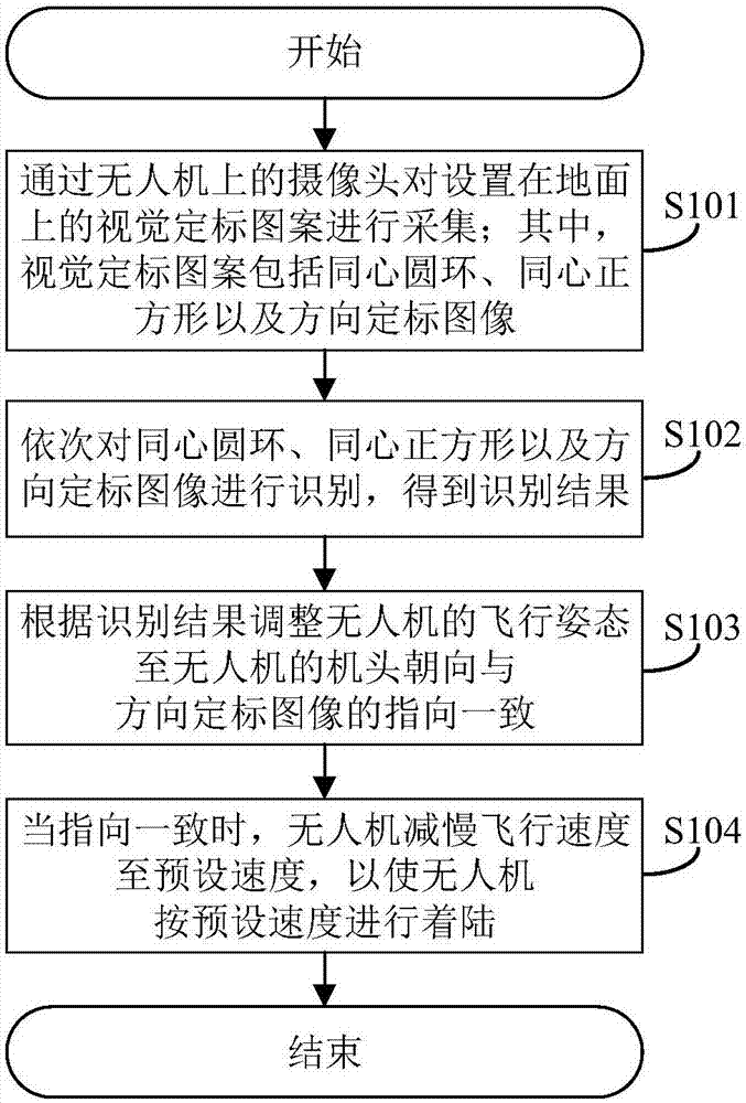
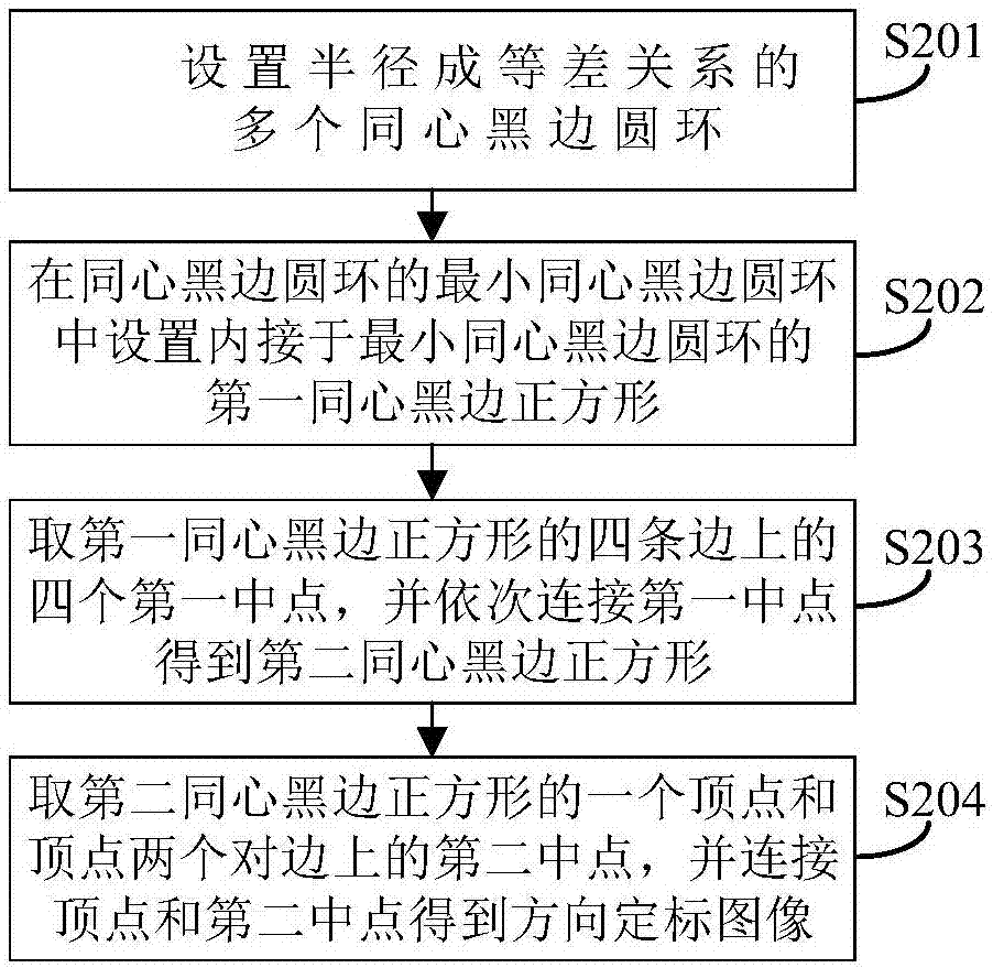
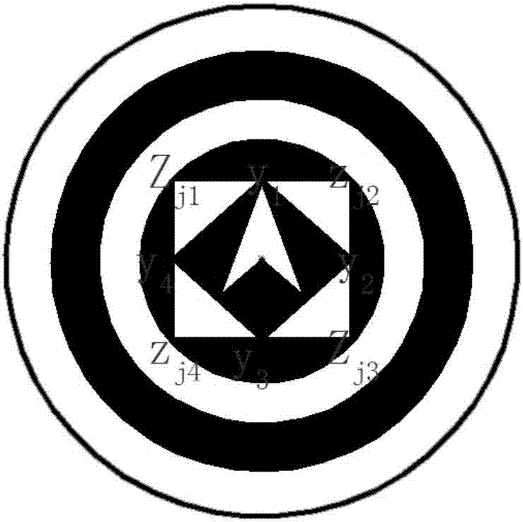
[0049] The core of this application is to provide a visual calibration method, system, and drone, which can enable the drone to recognize a visual calibration pattern with richer geometric features and easier image recognition, and improve unmanned The accuracy of autonomous landing of aircraft reduces the frequency of abnormal autonomous landing events.

[0050] In order to make the purpose, technical solutions and advantages of the embodiments of the present application clearer, the following will clearly and completely describe the technical solutions in the embodiments of the present application with reference to the drawings in the embodiments of the present application. Obviously, the described embodiments It is a part of the embodiments of this application, but not all the embodiments. Based on the embodiments in this application, all other embodiments obtained by those of ordinary skill in the art without creative work shall fall within the protection scope of this applic...


PUM


Abstract

The invention discloses a vision calibration method. The method comprises the steps of collecting a vision calibration pattern arranged on the ground through a camera on an unmanned aerial vehicle; identifying a concentric annulus, a concentric square and a direction calibration image in sequence to obtain identification results; according to the identification results, adjusting flight attitude of the unmanned aerial vehicle to enable the direction of the head of the unmanned aerial vehicle to be consistent with that of the direction calibration image; and when the direction of the head of the unmanned aerial vehicle is consistent with that of the direction calibration image, reducing the flight speed of the unmanned aerial vehicle to a preset speed, thereby enabling the unmanned aerial vehicle to land at the preset speed. According to the method, the unmanned aerial vehicle identifies the provided vision calibration pattern richer in geometric characteristic and easier to be subjected to image identification, so that the autonomous landing precision of the unmanned aerial vehicle is improved and the occurrence frequency of autonomous landing exception events is reduced. The invention furthermore discloses a vision calibration system and the unmanned aerial vehicle, which have the abovementioned beneficial effects.

Description

Technical field [0001] This application relates to the field of image recognition technology, and in particular to a method, system and unmanned aerial vehicle for visual calibration. Background technique [0002] With the development of science and technology, various UAVs are used more and more widely. Among them, intelligent UAVs rely on various devices installed on them to achieve autonomous landing and recovery, which will greatly reduce the long-distance Controlling the workload of personnel and improving work efficiency, but at the same time there will be interference and influence caused by various factors, resulting in the poor realization of the autonomous landing function of the UAV. [0003] At present, the prior art recognizes ground icons composed of multiple concentric squares, and recognizes each concentric square from large to small, and after the recognition is passed, it lands in the square with the most center and the smallest side length. Because only the geom...

Claims


Application Information

Patent Timeline
IPC IPC(8): G06K9/32
CPCG06V10/245
Inventor 罗晶苏成悦翁立宇
Owner GUANGDONG UNIV OF TECH
Why Eureka
Try Eureka