Argon blowing joint

A nozzle and rotary connection technology, applied in the field of argon blowing joints, can solve problems such as threats to workers' personal safety, molten steel splashing, etc., and achieve the effects of improving work efficiency, reducing the number of parts, and shortening installation time.

Inactive Publication Date: 2017-09-26
YANGZHONG FIRST BUTTERFLY VALVE FACTORY
View PDF4 Cites 0 Cited by
  • Summary
  • Abstract
  • Description
  • Claims
  • Application Information

AI Technical Summary

Problems solved by technology

[0002] The argon blowing device in the prior art basically completes the butt joint of the joint by manpowe

Method used


Image

  • Argon blowing joint
  • Argon blowing joint

Examples


Example Embodiment

[0016] The present invention will be further described below in conjunction with the accompanying drawings. The following embodiments are only used to illustrate the technical solutions of the present invention more clearly, and cannot be used to limit the protection scope of the present invention.

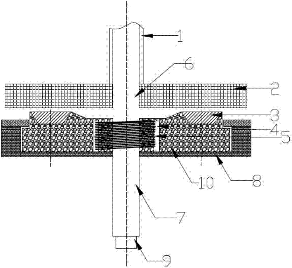
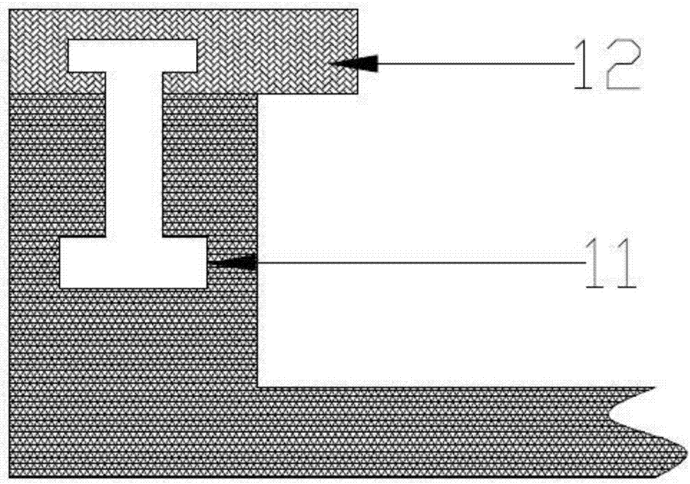
[0017] An argon blowing joint, comprising an upper fixed plate 2, an upper tube 6, a lower tube 7, a number of limit parts 12, a bearing seat 8 and a floating seat 10; the upper fixed plate 2, the floating seat 10 and the The supporting bases 8 are arranged coaxially from top to bottom in turn. The supporting base 8 is provided with a containing groove for accommodating the floating base 10, and the cross-section of the supporting base 8 is "U"-shaped. A number of the limiting portions 12 are rotatably connected to the top wall of the 8, and a number of the limiting portions 12 are arranged at equal intervals around the axis of the bearing seat 8, the floating seat 10 is cylindrical i...


PUM


Abstract

The invention relates to an argon blowing joint, and belongs to the technical field of steel making auxiliary equipment. The argon blowing joint comprises an upper fixed plate, an upper pipe, a lower pipe, multiple limiting parts, a bearing base and a floating base; the upper fixed plate, the floating base and the bearing base are sequentially and coaxially arranged from top to bottom, a containing groove used for containing the floating base is formed in the bearing base, the multiple limiting parts are rotatably connected to the top wall of the bearing base, and are arranged around the axis of the bearing base at equal distances, the floating base is cylindrical, an annular hole matched with the limiting portions is formed in the upper side wall of the floating base along the axis from outside to inside, and the length of the limiting portions is larger than the sum of the thickness of the side wall of the bearing base and the gap between the bearing base and the floating base; the upper pipe penetrates the axis of the upper limiting plate to be communicated with the lower pipe, and the lower end of the lower pipe penetrates the floating base and the bearing base to be communicated with the exterior environment. An existing argon blowing joint structure is simplified, the number of assembled components is greatly reduced, the mounting step is simplified, mounting time is shortened, and work efficiency is improved.

Description

technical field [0001] The invention relates to an argon blowing joint, which belongs to the technical field of auxiliary equipment for steelmaking. Background technique [0002] The argon blowing device in the prior art basically completes the butt joint of the joints by manpower, because molten steel may splash out during transportation, threatening the personal safety of workers. Contents of the invention [0003] The technical problem to be solved by the present invention is to overcome the defects of the prior art and provide an argon blowing joint, which can realize butt joint automatically. [0004] In order to achieve the above purpose, the present invention provides an argon blowing joint, which includes an upper fixing plate, an upper tube, a lower tube, several limiting parts, a bearing seat and a floating seat; the upper fixing plate, the floating seat and the The bearing seats are arranged coaxially from top to bottom in turn, and a receiving groove for accom...

Claims


Application Information

Patent Timeline
IPC IPC(8): C21C7/072
CPCC21C7/072
Inventor 许瑞华
Owner YANGZHONG FIRST BUTTERFLY VALVE FACTORY
Why Eureka
Try Eureka