Flexible mount for coupling force actuator to caliper jaw

a coupling force actuator and flexible technology, applied in the field of precision measurement instruments, can solve the problems of unreliable or non-repeatable measurement of objects, the variation of force which can be applied by the measuring jaw, and the differences in measurement which can occur, so as to reduce the parts count and assembly cost, and increase the available flex range

Active Publication Date: 2015-10-01
MITUTOYO CORP
View PDF7 Cites 18 Cited by
  • Summary
  • Abstract
  • Description
  • Claims
  • Application Information

AI Technical Summary

Benefits of technology

[0010]In various implementations, the flexible element comprises parallel spring elements that bend primarily in a plane parallel to the measuring axis direction. In one specific example implementation, steel shims may be utilized for the parallel spring elements. In other implementations, other material types (e.g., a resilient polymer material) may be used to provide the flexible element, which may be formed as a combination of parts or elements (e.g., a stamped metal flexure molded into a polymer part) or as a single element (e.g., a single molded part) to reduce the parts count and assembly cost. In one implementation, a compound flexure may be utilized for the flexible element with a resulting increase in the available flex range. In various implementations, the materials and configuration of the flexible mount may be selected such that a relative displacement of at least 0.5 mm and at most 5.0 mm corresponds to a related change in the measuring force of at least 0.1 newtons and at most 10 newtons.

Problems solved by technology

As described in the '009 publication, one deficiency in the use of prior calipers is the variation in force which can be applied by the measuring jaws and the differences in measurement which can occur as a result.
Particularly when a soft object is being measured, the measurement of the object may be unreliable or non-repeatable because one may apply either a higher force on the jaws of the caliper such that the soft object is “more compressed”, or apply a lower force such that the soft object is “less compressed”.
However, the force sensing and indicating features of the caliper of the '009 publication may be considered “overkill” in many applications, and / or may be considered too expensive and / or complex by many caliper users.

Method used


Image

  • Flexible mount for coupling force actuator to caliper jaw
  • Flexible mount for coupling force actuator to caliper jaw
  • Flexible mount for coupling force actuator to caliper jaw

Examples


Embodiment Construction

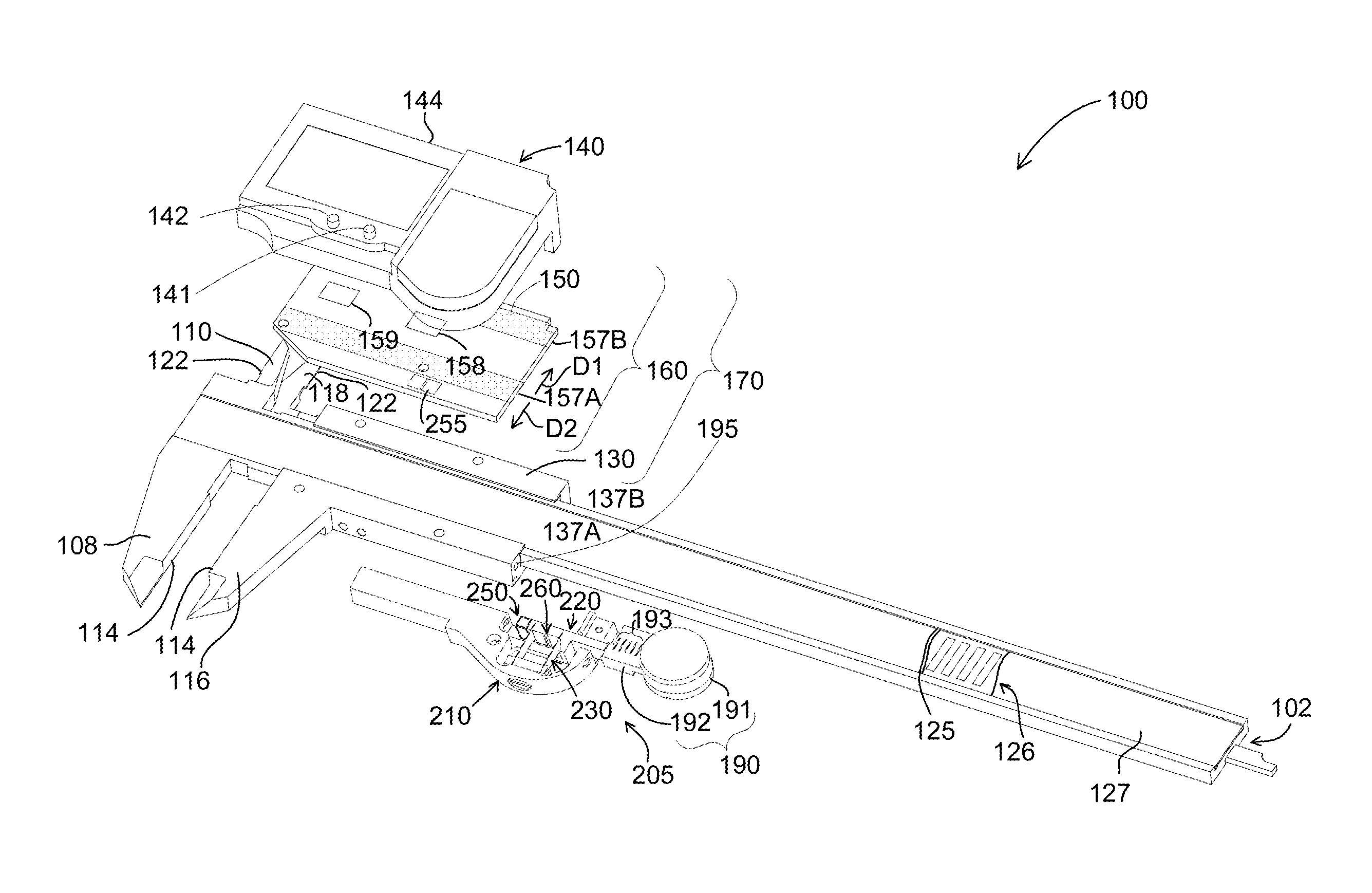
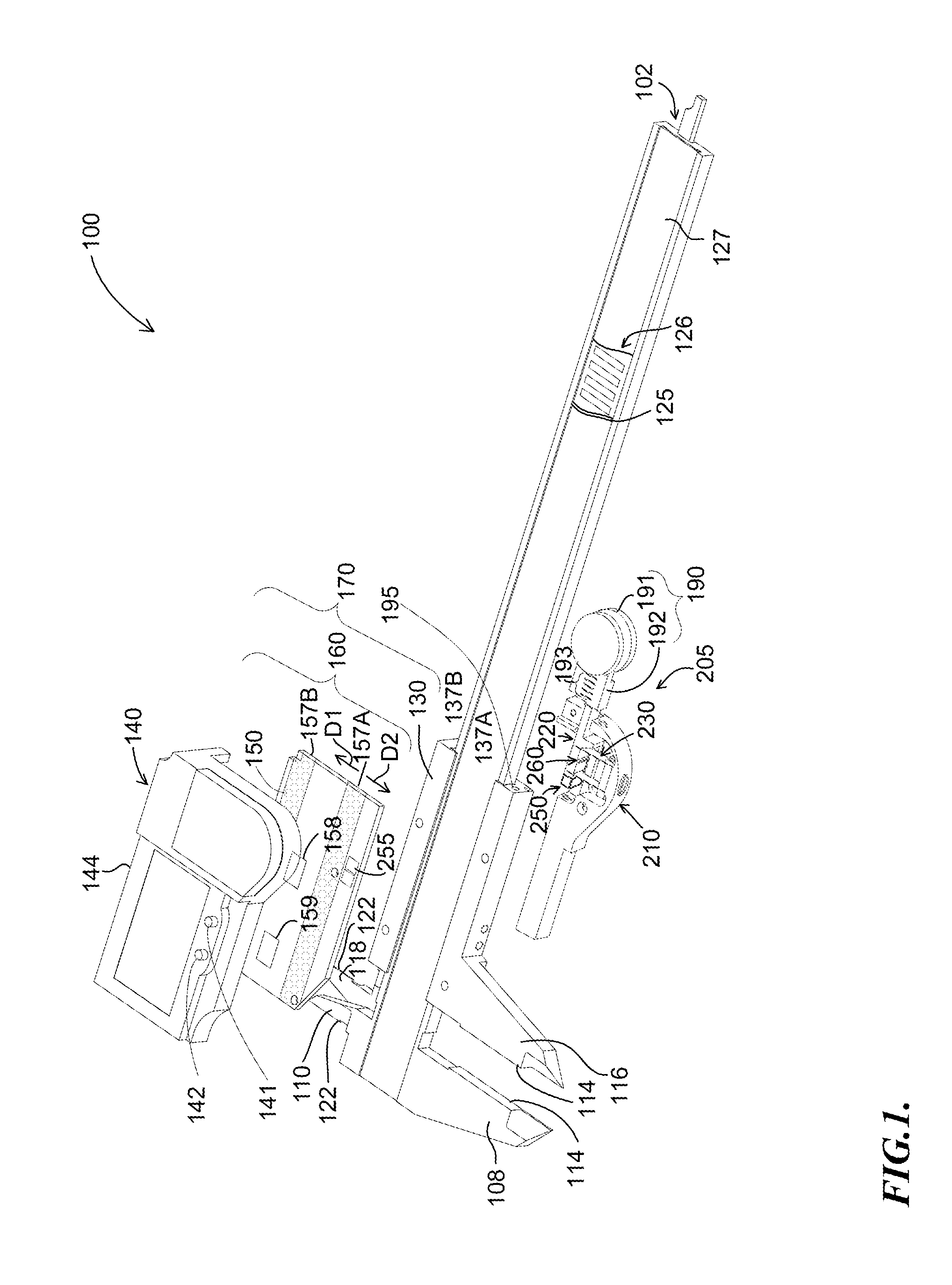
[0019]FIG. 1 is an exploded isometric view diagram of a hand tool type caliper 100 with a flexible mount 205 for coupling a force actuator assembly 190 to a slider 130 with caliper jaws 116 and 118. In this example, the caliper 100 comprises a slider displacement sensor 158 (e.g., a magnetic or inductive sensor assembly) and a scale substrate 125 including a scale track 126 (a cut-away segment of each is illustrated) positioned in a groove 127 along an elongated scale member 102. It will be appreciated that in other embodiments other types of slider displacement sensors 158 may be utilized (e.g., capacitive, etc.) A slider assembly 170 includes an electronic assembly 160 attached to a slider 130. The slider displacement sensor 158 is included in the electronic assembly 160. The general mechanical structure and physical operation of the caliper 100 is similar to that of certain prior electronic calipers, such as that of commonly assigned U.S. Pat. No. 5,901,458, which is hereby incor...


PUM


Abstract

A flexible mount is provided for coupling a force actuator to a caliper jaw. The flexible mount includes a first mounting portion for being coupled to the caliper jaw, a second mounting portion for being coupled to the force actuator, and a flexible element (e.g., a parallel flexure) coupled between the first and second mounting portions. When a force is applied to the force actuator (e.g., by a user pushing on a thumbwheel) along the measuring axis direction, the flexible element flexes to generate a measuring force that is applied to the caliper jaw. The use of the flexible mount results in more control and a better feel for a user when attempting to exert control to provide a desired amount of force during a measuring process. The flexible mount may also utilize a fastening configuration that is compatible with existing mounting features on existing caliper jaws.

Description

BACKGROUND[0001]1. Technical Field[0002]The invention relates generally to precision measurement instruments, and particularly to calipers with a movable jaw for measuring the dimensions of an object.[0003]2. Description of the Related Art[0004]Calipers are known that utilize pairs of jaws for determining measurements. A first jaw is generally fixed at one end of a measurement scale while a second jaw is attached to a slider assembly that moves along the measurement scale. An outer dimension of an object may be measured by arranging the object between and against inner surfaces of the first and second jaws. An inner dimension of an object may be measured by arranging outer surfaces of the first and second jaws between and against the inner surfaces of the object (e.g. the walls of a hole). The slider assembly may be moved with a user's thumb, and a thumb wheel may be provided for enabling controlled movement of the slider. One exemplary caliper utilizing a thumb wheel is described i...

Claims


Application Information

Patent Timeline
Patent Type & Authority Applications(United States)
IPC IPC(8): G01B3/20
CPCG01B3/205G01B3/008G01B3/18G01B3/20G01B3/22G01B5/00G01B5/02G01B5/08G01B5/12G01B5/14G01D5/12
Inventor EMTMAN, CASEY E.GOLDSWORTHY, MICHAEL EDWARDGARRITY, WILLIAM RANDALL
Owner MITUTOYO CORP
Why Eureka
Try Eureka