Color film substrate, display panel and device

A color film substrate and display panel technology, applied in optics, instruments, nonlinear optics, etc., can solve the problems of reducing the contrast of the panel, achieve the effect of reducing reflection without affecting the display brightness

Inactive Publication Date: 2017-09-26
BOE TECH GRP CO LTD
View PDF5 Cites 9 Cited by
  • Summary
  • Abstract
  • Description
  • Claims
  • Application Information

AI Technical Summary

Problems solved by technology

However, when the wire grid polarizer is applied to the color filter side, the am

Method used


Image

  • Color film substrate, display panel and device
  • Color film substrate, display panel and device
  • Color film substrate, display panel and device

Examples


Embodiment Construction

[0027] Embodiments of the present invention are described in detail below, examples of which are shown in the drawings, wherein the same or similar reference numerals designate the same or similar elements or elements having the same or similar functions throughout. The embodiments described below by referring to the figures are exemplary only for explaining the present invention and should not be construed as limiting the present invention. Also, detailed descriptions of known arts will be omitted if they are unnecessary to illustrate the features of the present invention.

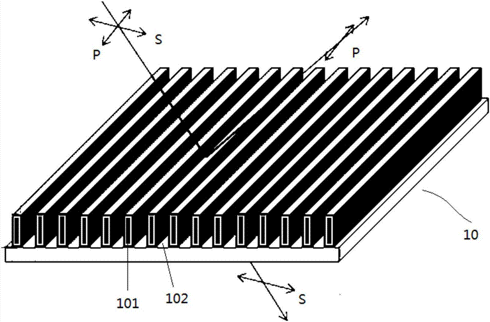
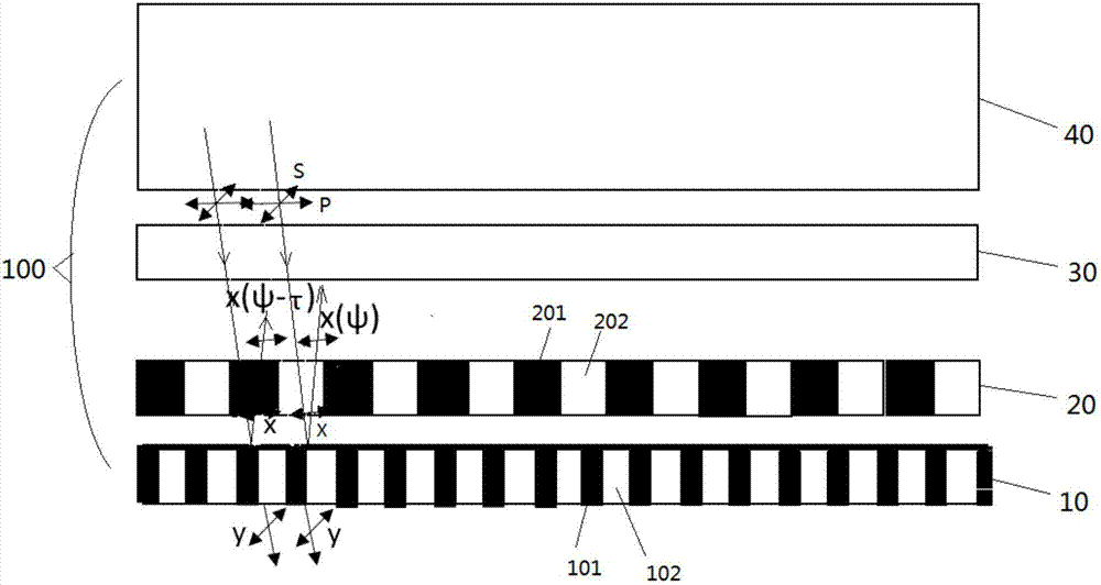
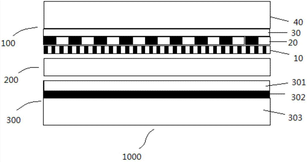
[0028] see figure 2 , the color filter substrate 100 of the present invention includes an upper substrate layer 40 , a color filter layer 30 , a phase difference layer 20 and a first wire grid polarizer 10 which are sequentially stacked. Specifically, the phase difference layer 20 includes several first phase shift structures 201 and second phase shift structures 202 arranged alternately, preferably, th...


PUM


Abstract

The invention provides a color film substrate which comprises a color film layer, a phase difference layer and a first wire grating polarizer which are sequentially laminated. The phase difference layer comprises a plurality of first phase shift structures and second phase shift structures which are arranged alternately. The phase difference layer enables P light passing the phase shift structures and P light passing the second phase shift to generate a phase difference, and thus a P light reflecting effect can be reduced. Meanwhile, S light passing the phase difference layer and the first wire grating polarizer has no phase difference, and thus brightness of the S light is not affected. In addition, the invention further provides a display panel to which the color film substrate is applied and a corresponding display device. The display panel and the display device have the advantages of reducing a light reflection effect and not affecting display brightness.

Description

technical field [0001] The present invention relates to the field of display technology. Specifically, the present invention relates to a color filter substrate, and also relates to a display panel and a display device using the color filter substrate. Background technique [0002] WGP (wire grid polarizer, that is, wire grid polarizer) is currently widely used in the display field, and its structure is as follows figure 1 As shown, the wire grid adopts metal materials with high conductivity, such as Al. The wire grid of the wire grid polarizer adopts slit distribution, that is, gaps are formed between adjacent wire grids. Usually, the width of the wire grid is about 50 nm, the width of the slot is about 50 nm, and the height of the wire grid is about 150 nm. The light splitting principle of the wire grid polarizer is: when the external natural light (which can be considered as a combination of orthogonal light in the plane perpendicular to the propagation direction) irradi...

Claims


Application Information

Patent Timeline
IPC IPC(8): G02F1/1335G02B1/11
CPCG02B1/11G02F1/133514G02F1/133528G02F2413/05G02F1/133548G02F1/133631G02F1/13363G02F1/13439G02F1/1368G02F2413/01G02F1/133531
Inventor 赵伟利柳在健
Owner BOE TECH GRP CO LTD
Why Eureka
Try Eureka