Antenna field calibration system and method

An on-site calibration, antenna technology, applied in the field of communication, can solve the problems of long time consumption, increased uncertainty of antenna pattern measurement, difficulty in long-distance alignment, etc., to achieve accurate calibration, good environmental adaptability and operability. Effect

Inactive Publication Date: 2021-08-13
BEIJING INST OF RADIO METROLOGY & MEASUREMENT
View PDF7 Cites 5 Cited by
  • Summary
  • Abstract
  • Description
  • Claims
  • Application Information

AI Technical Summary

Problems solved by technology

[0004] 1. Every time the antenna pattern is to be tested, it is necessary to find the phase center of the antenna at this frequency point, and coincide the phase center with the rotation axis center of the turntable. Generally, it needs to be moved repeatedly several times to find the position of the phase center. so it takes a very long time
[0005] 2. The phase center of the antenna under test is not the same at each test frequency point, so when measuring the amplitude pattern at each test frequency point, it is necessary to repeat the operation of finding the phase center at each test frequency point. It is very cumbersome and time-consuming. If the pattern test has a lot of test frequency points, the efficiency is relatively low.
[0006] 3. 26.5GHz-40GHz far-field measurement pattern, the distance between the transmitting antenna and the receiving antenna is long, and the signal attenuation per unit distance in the 26.5GHz-40GHz frequency band is large, resulting in a small measurement signal. In addition, the main beam of the high-gain antenna is relatively narrow. This requires strict alignment of the transmitting and receiving antennas. Due to the small size, long-distance alignment is difficult, and these factors will increase the uncertainty of the antenna pattern measurement.
[0007] 4. The 26.5GHz-40GHz far-field measurement pattern needs to be carried out in a darkroom environment. The reflection of electromagnetic waves by surrounding objects will lead to inaccurate measurements. Therefore, the antennas need to be transported to the darkroom environment for measurement. For base or model antennas , had to be disassembled and transported to a darkroom to be measured, which increased the risk of transportation on the way

Method used


Image

  • Antenna field calibration system and method
  • Antenna field calibration system and method
  • Antenna field calibration system and method

Examples


Embodiment Construction

[0032] In order to illustrate the present invention more clearly, the present invention will be further described below in conjunction with preferred embodiments and accompanying drawings. Similar parts in the figures are denoted by the same reference numerals. Those skilled in the art should understand that the content specifically described below is illustrative rather than restrictive, and should not limit the protection scope of the present invention.

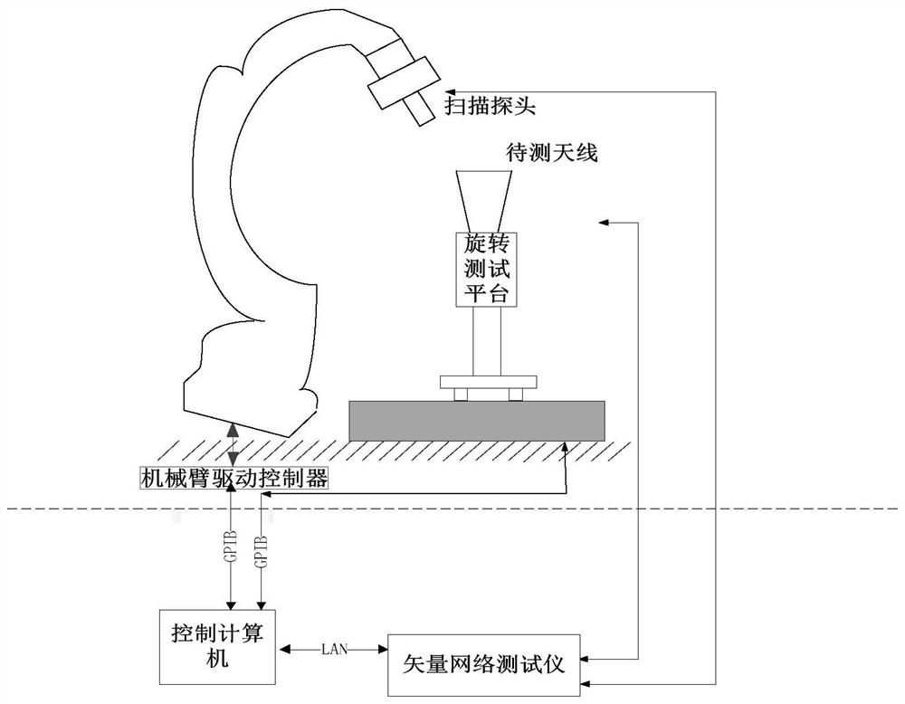
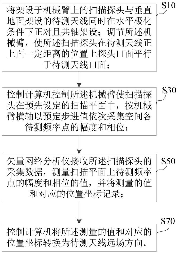
[0033] The principle of the present invention is to set up the waveguide probe (machine scanning probe) on the mechanical arm, the base of the mechanical arm is designed to be movable, the antenna to be tested is erected perpendicular to the ground, the mechanical arm is loaded with the waveguide probe, and the distance from the antenna to be tested is about 60mm and Within the near-field rectangular area of ​​the plane parallel to the antenna to be tested, use the scanning probe to collect the amplitude and phase informati...


PUM


Abstract

The embodiment of the invention discloses an antenna field calibration system and method, and the system comprises a to-be-tested antenna which is erected in a manner of being vertical to the ground and is used for transmitting electromagnetic waves which are transmitted upwards in the direction vertical to the ground; a scanning probe which is erected on a mechanical arm, directly faces and is coaxially erected with the to-be-tested antenna under the horizontal polarization condition at the same time, and is used for scanning electromagnetic waves emitted by the to-be-tested antenna; a control computer which is used for adjusting the mechanical arm, so that the probe opening surface of the scanning probe is parallel to the opening surface of the to-be-detected antenna at a position with a certain distance right above the to-be-detected antenna, and controlling the mechanical arm to enable the scanning probe to sequentially collect the amplitude and phase of each to-be-measured frequency point in the space at a preset stepping value according to the transverse axis of the mechanical arm in a preset scanning plane; and a vector network analyzer which is used for receiving acquired data of the scanning probe, measuring amplitude and phase values of the to-be-measured frequency points on a scanning plane, and recording the measured values and corresponding position coordinates; wherein the control computer converts the measured values and the corresponding position coordinate into a far-field pattern of the to-be-tested antenna.

Description

technical field [0001] The present invention relates to the field of communication. More specifically, it relates to an antenna field calibration system and method. Background technique [0002] The IEEE Std 149 standard specifies the antenna pattern calibration method. Antenna calibration is carried out in a microwave anechoic room. The transmitting antenna and the receiving antenna are set up on the antenna bracket coaxially. The distance between the transmitting antenna and the receiving antenna is d, d Satisfy the far-field condition. Adjust the phase center of the antenna under test to coincide with the center of the turntable. [0003] For 26.5GHz-40GHz antennas, the IEEE Std 149 standard is used to measure the amplitude pattern, and there are the following deficiencies: [0004] 1. Every time the antenna pattern is to be tested, it is necessary to find the phase center of the antenna at this frequency point, and coincide the phase center with the rotation axis cent...

Claims


Application Information

Patent Timeline
Patent Type & Authority Applications(China)
IPC IPC(8): G01R29/10
CPCG01R29/105
Inventor 刘星汛黄承祖成永杰齐万泉颉逍白伟
Owner BEIJING INST OF RADIO METROLOGY & MEASUREMENT
Why Eureka
Try Eureka