Phase shifter assembly

a phase shifter and assembly technology, applied in the direction of antenna details, electrical equipment, antennas, etc., can solve the problems of increasing the size and cost of the phase shifter system, the effect of reducing the size of the phase shifter assembly, reducing the cost, and improving the sidelobe suppression

Active Publication Date: 2019-01-10
COMMSCOPE TECH LLC
View PDF6 Cites 5 Cited by
  • Summary
  • Abstract
  • Description
  • Claims
  • Application Information

AI Technical Summary

Benefits of technology

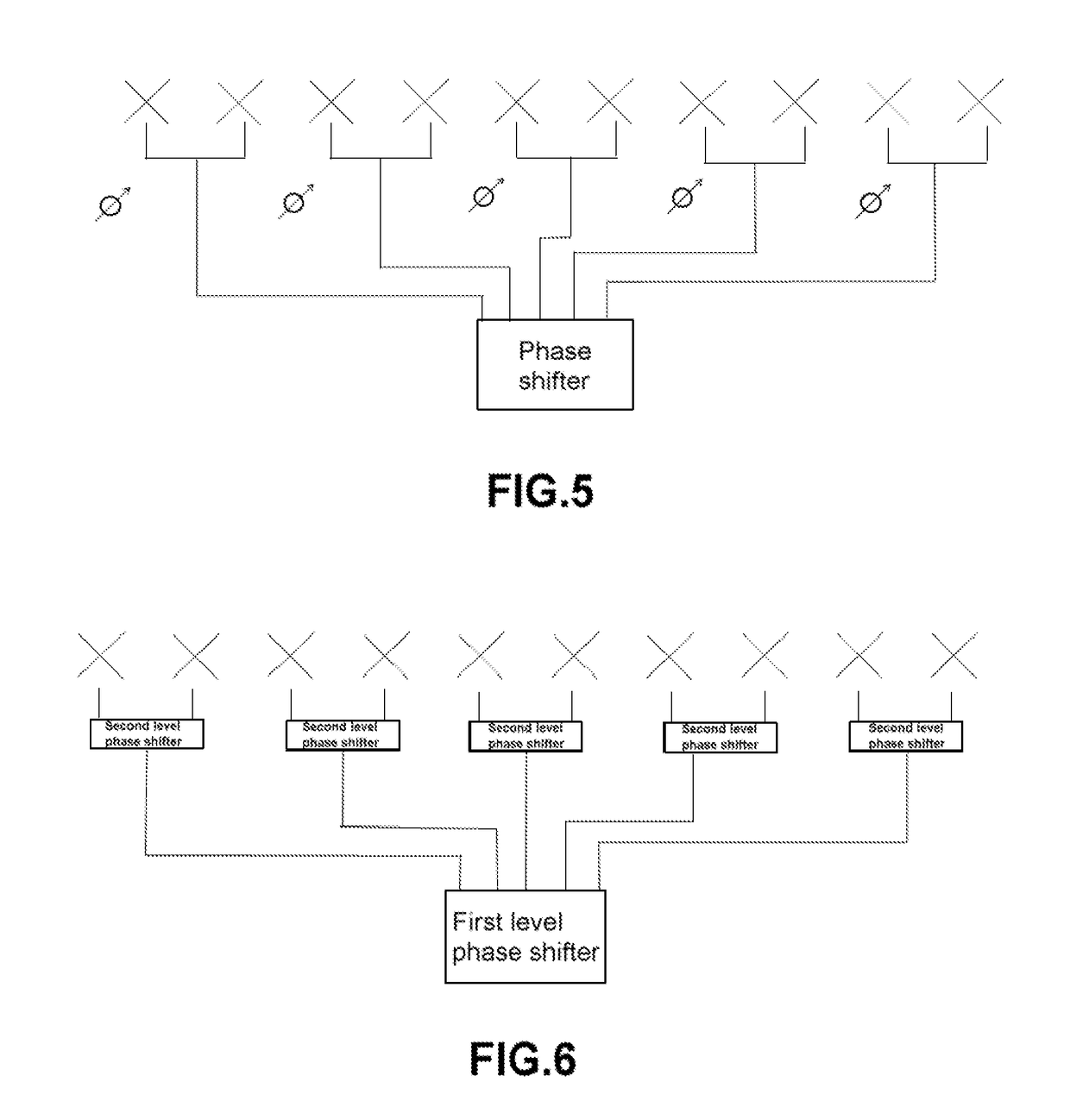
[0016]In view of the aforementioned disadvantages in the prior art, embodiments of the present invention provide phase shifter assemblies for base station array antennas which may have the advantages of both a distributed phase shifter network and a lumped phase shifter network. Specifically, the phase shifter assemblies according to embodiments of the present invention can independently control the phases of the radiating elements in the array to obtain better sidelobe suppression. Further, phase control parts of the phase shifter are concentrated within a certain physical space range, so the size of the phase shifter assembly may be greatly decreased, and the cost may be greatly reduced, as compared with a conventional distributed phase shifter assembly design.
[0020]In some embodiments, the power divider may be a Wilkinson power divider. The use of Wilkinson power dividers may reduce the reflection effects caused by the matching problem between the ports of the phase shifter, provide higher linearity for the phases in the entire transmission link, and also provide improved smoothness for the amplitudes, which may be conducive to improving the forming effect of a directional diagram of the array antenna.
[0023]Therefore, the phase shifter assembly according to embodiments of the present invention can provide different amplitudes and phases for the output ports to feed back independent amplitudes and phases to each radiating element in the array antenna. By adopting the phase shifter assembly according to the present invention, standard Chebyshev, Taylor and binomial distribution of the array antenna can be achieved within the range of the entire downtilt angle, and the vertical plane directional diagram of the array antenna has a good forming effect, so as to meet the requirements of low sidelobe and high gain. Moreover, on the premise of supporting transmission expansion, graded phase shift can be expanded at any output port again to meet the demands of the array antennas with different numbers of radiating elements.
[0024]In some embodiments, the first level phase shifter, the second level phase shifter and / or the power divider may be integrated on one printed circuit board (“PCB”). Therefore, the overall size of the phase shifter assembly can be greatly reduced.
[0025]In some embodiments, the ports in the phase shifter assembly may be disposed in parallel. Therefore, superposition of phase shift error of each level may be eliminated, and thus the ports achieve may achieve more accurate phase linearity.

Problems solved by technology

Moreover, with the increasing complexity of geographical and electromagnetic application environments, the requirements on the cost of a base station antenna and on such performance indexes as high gain, low sidelobe and the like are also steadily increasing.
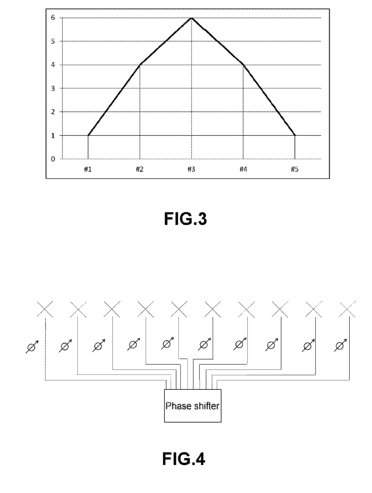
The disadvantages of this structure are it requires a greater number of individual phase shifters (namely one for each radiating element) resulting in a large size and an increased cost for the phase shifter system.
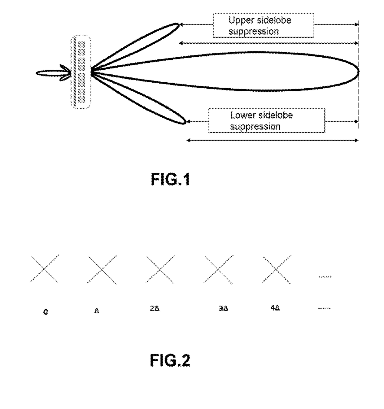
The disadvantages of this structure lie in that as the phases of all of the radiating elements in the array cannot be independently controlled, and hence the sidelobe suppression may be worse.
In addition, the existing multi-port phase shifter generally adopts a serial form, and a level of phase shift error will be superimposed once a level of phase shifter is additionally connected in series, such that when the phase shifter is connected to the array antenna, the phase error of output ports of the phase shifters on both ends may be larger, and the phase error of each radiating element in the array antenna may be inconsistent.

Method used


Image

  • Phase shifter assembly
  • Phase shifter assembly
  • Phase shifter assembly

Examples


first embodiment

[0044]FIGS. 7 to 9 illustrate a first embodiment of a phase shifter assembly according to the present invention. As shown in FIG. 7, the first level phase shifter is located in an Area A, two arc members R1 and R2 are in coupled connection by a rotatable wiper arm S1 (reference can be specifically made to FIG. 8), and the phases are changed by sliding of the rotatable wiper arm S1 on the arc members R1 and R2.

[0045]As shown in FIG. 7, the second level phase shifter is located in an area B and also adopts a combined structure of a rotatable wiper arm S2 (reference can be specifically made to FIG. 9) and the arc member, but only one arc member is provided, and the phase between two connected ports is changed by sliding of the rotatable wiper arm S2 on the arc member.

[0046]As shown in FIG. 7, a Wilkinson power divider is located in an area C, the Wilkinson power divider can be an unequal power divider or an equal power divider, and the isolation of two ports can be improved by adding a...

second embodiment

[0055]FIGS. 10 to 11 illustrate a second embodiment of a phase shifter assembly according to the present invention. In the discussion that follows, the description of the second embodiment will focus on the features of the second embodiment, and same components as in the first embodiment are represented by the same reference signs in the first embodiment and will not be described below in detail.

[0056]As shown in FIG. 10, the first level phase shifter is located in an area D, two arc members are in coupled connection by a rotatable wiper arm S1 (reference can be specifically made to FIG. 11), and the phases are changed by sliding the rotatable wiper arm on the arc members.

[0057]As shown in FIG. 10, a Wilkinson power divider is located in an area E, the Wilkinson power divider can be an unequal power divider or an equal power divider, and the isolation of the two output ports of each Wilkinson power divider may be improved by adding a resistor so as to further improve the directional...


PUM


Abstract

The present invention provides a phase shifter assembly for an array antenna, comprising: a first level phase shifter, wherein the first level phase shifter is configured to control the phases of a plurality of sub-arrays of the array antenna, where each sub-array comprises one or more radiating elements; a second level phase shifter, wherein the second level phase shifter is configured to proportionally change the phases of the radiating elements in the corresponding sub-arrays; and a power divider, wherein the power divider is connected between the first level phase shifter and the second level phase shifter. The phase shifter assembly has the advantages of both a distributed phase shifter network and a lumped phase shifter network. Specifically, the phase shifter assemblies can independently control the phases of the radiating elements in the array to obtain better sidelobe suppression. Further, phase control parts of the phase shifter are concentrated within a certain physical space range, so the size of the phase shifter assembly may be greatly decreased, and the cost may be greatly reduced, as compared with a conventional distributed phase shifter assembly design.

Description

FIELD OF THE INVENTION[0001]The present invention generally relates to a phase shifter assembly for a base station array antenna.BACKGROUND OF THE INVENTION[0002]The current development of mobile communications changes with each passing day and has rapidly entered a 4G era from a 3G era, and the popularity rate of mobile phones is very high and is increasing year by year. Moreover, with the increasing complexity of geographical and electromagnetic application environments, the requirements on the cost of a base station antenna and on such performance indexes as high gain, low sidelobe and the like are also steadily increasing. Base station antennas are typically implemented as phased array antennas that have a plurality of individual radiating elements that are disposed in one or more columns.[0003]In order to change the coverage of the base station antenna, a mobile operator usually changes the elevation or “tilt” angle of the base station antenna. Currently, a mainstream base stat...

Claims


Application Information

Patent Timeline
Patent Type & Authority Applications(United States)
IPC IPC(8): H01Q3/32H01P1/18H01Q1/24
CPCH01Q3/32H01Q1/246H01P1/184
Inventor LI, YUEMINWEN, HANGSHENGLI, HAIFENG
Owner COMMSCOPE TECH LLC
Why Eureka
Try Eureka