Section-line recognition device

A lane line recognition, lane line technology, applied in character and pattern recognition, vehicle components, transportation and packaging, etc., can solve problems such as increased deviation, reduced driving control controllability, and low recognition accuracy.

Active Publication Date: 2017-09-26
DENSO CORP +1
12 Cites 2 Cited by

AI-Extracted Technical Summary

Problems solved by technology

On the other hand, when the recognition accuracy of the driving lane line recognized from the image is low, the deviation between the long-distance white line shape obtained by estimation and the actual white line shape increases.
U...

Abstract

A section-line recognition device (10) is applicable to a vehicle installed with an image-capturing device (21) for capturing images in front of the vehicle. The section-line recognition device (10) is provided with: a section-line recognition unit (11) for recognizing, on the basis of images acquired by the image-capturing device (21), travel section lines for dividing vehicle travel lanes; and a section-line estimation unit (12) for estimating, on the basis of the travel section lines recognized by the section-line recognition unit (11), the shape of travel section lines of such scope as to be incapable of being recognized by the section-line recognition unit (11). The section-line recognition device (10) determines the reliability of the travel section lines recognized by the section-line recognition unit (11), and invalidates the estimate of the shape of the travel section lines by the section-line estimation unit (12) on the basis of the determination result.

Application Domain

Image analysisPedestrian/occupant safety arrangement +3

Technology Topic

Image captureIdentification device +1

Image

  • Section-line recognition device
  • Section-line recognition device
  • Section-line recognition device

Examples

  • Experimental program(1)

Example

[0015] (First embodiment)
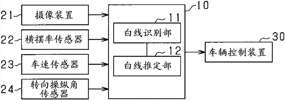
[0016] Hereinafter, the lane marking recognition device of this embodiment will be described with reference to the drawings. The lane line recognition device of this embodiment is a device mounted on a vehicle. The lane line recognition device recognizes a white line that is a driving lane line dividing the driving lane of the vehicle. Information related to the white line recognized by the lane line recognition device (for example, white line information) is used to follow the preceding vehicle as a vehicle traveling in the same lane as the own vehicle among the preceding vehicles traveling in front of the own vehicle Drive assist control such as adaptive cruise control, lane keeping assist that controls the vehicle’s travel so that the vehicle does not deviate from the lane line. First, use figure 1 A brief configuration of the lane line recognition device of this embodiment will be described.
[0017] figure 1 The system shown is a system mounted on a vehicle, and has the lane line recognition device 10 of this embodiment. in figure 1 Among them, the lane line recognition device 10 is a computer equipped with CPU, ROM, RAM, I/O, etc., and each function of the lane line recognition device 10 (for example, lane line recognition unit, lane line Presumption unit, reliability determination unit, and presumption invalid unit). The vehicle (that is, the host vehicle) is equipped with an imaging device 21 as an object detection unit that detects objects existing around the vehicle. The lane line recognition device 10 inputs an image captured by the camera 21, and uses the input image to create white line information.
[0018] The imaging device 21 is a vehicle-mounted camera, and is composed of a CCM camera, a CMOS image sensor, a near infrared camera, and the like. The imaging device 21 captures the surrounding environment including the driving road of the vehicle, generates image data representing the captured image, and sequentially outputs the image data to the lane line recognition device 10. The imaging device 21 is installed in the vicinity of the upper end of the windshield of the host vehicle, for example, and takes an image of an area that extends toward the front of the vehicle to a predetermined imaging angle δ1 with the imaging axis as the center. In addition, the imaging device 21 may be a monocular camera or a stereo camera.
[0019] The lane line recognition device 10 inputs image data from the imaging device 21 and respectively inputs detection signals of various sensors provided in the vehicle. in figure 1 In the system shown, various sensors are provided with a yaw rate sensor 22 that detects the angular velocity (for example, yaw rate) of the vehicle toward the steering direction, a vehicle speed sensor 23 that detects vehicle speed, and a steering angle sensor that detects steering angle. 24 and so on. The vehicle speed sensor 23 corresponds to a vehicle speed detection unit. The yaw rate sensor 22 and the steering angle sensor 24 correspond to a steering detection unit.
[0020] The lane line recognition device 10 includes a white line recognition unit 11 and a white line estimation unit 12. The white line recognition unit 11 recognizes white lines located in the image captured by the imaging device 21. The white line estimating unit 12 uses the information related to the white line recognized by the white line recognition unit 11 to estimate the shape of the white line in the range not recognized by the white line recognition unit 11, that is, the white line recognition unit 11 The shape of the white line farther away.
[0021] figure 2 It is a flowchart showing the processing procedure of the white line recognition process executed by the lane line recognition device 10. This process is repeatedly executed by the CPU of the lane line recognition device 10 in a predetermined control cycle. Through this process, a white line recognition unit 11 equivalent to a lane line recognition unit (for example, a lane line recognition unit), a lane line estimation unit (for example, a lane line estimation unit), and a reliability determination unit (for example, reliability The functions of the white line estimation unit 12 corresponding to the determination unit) and the estimated invalid unit (for example, the estimated invalid unit).
[0022] in figure 2 In step S10, an image captured by the imaging device 21 is acquired. In the next step S11, the edge point P is extracted based on the brightness information of the road image in the acquired image, and in step S12, the extracted edge point P is Hough transformed. Here, extraction of straight lines or curves in which a plurality of edge points P are continuously arranged is performed. In the next step S13, the extracted straight lines or curves are used as white line candidates, and their feature values ​​are calculated. In step S14, the feature values ​​are used to extract the white line candidates that extend in the direction of travel of the vehicle. For straight or curved lines.
[0023] Next, in step S15, the bird's-eye view conversion of the edge point P is performed. Specifically, the edge point P of the extracted white line candidate is converted into a plan view by coordinate conversion using the installation position and the installation angle of the imaging device 21. It should be noted that in the obtained plan view, the range where the white line is located is the "white line recognition range". That is, the shape of the white line from the host vehicle to the short distance D1 can be recognized from the image captured by the imaging device 21, and the position of the recognized white line farthest from the host vehicle is the end of the white line recognition range. The plan view is an orthogonal coordinate system of the center of the host vehicle with the vehicle width direction of the host vehicle as the X axis and the traveling direction of the vehicle as the Y axis.
[0024] In the next step S16, it is estimated that the white line parameter η (for example, the position of the white line, the slope of the white line, the width of the white line, the curvature of the white line, and the change in the curvature of the white line) to be converted into the white line shape of the plan view is estimated Rate etc.). The estimation of the white line parameter η is performed by approximating the shape of the white line converted into a plan view using a polynomial (for example, a white line model).
[0025] Next, in step S17, by extrapolating the white line parameter η, the white line outside the white line recognition range, that is, the white line farther than the close distance D1 (hereinafter also referred to as "distant white line") is estimated. shape. The estimation of the shape of the distant white line is performed by a white line model using the white line parameter η, for example, using at least one of the curvature of the white line and the curvature change rate (for example, a cyclotron parameter). In addition, the white line model may be an approximation based on a polynomial, or a table, etc. The white line parameters of the estimated white line are stored, and this routine is ended. In this embodiment, by the processing of steps S10 to S15 performed by the lane line recognition device 10, the function of the white line recognition unit 11 equivalent to the lane line recognition unit can be realized. In addition, by the processing of steps S16 and S17 performed by the lane line recognition device 10, the function of the white line estimating unit 12 corresponding to the lane line estimating unit can be realized.
[0026] back to figure 1 In the description, the information related to the white line recognized by the white line recognition unit 11 and the information related to the distant white line estimated by the white line estimating unit 12 are input to the vehicle control device 30. The vehicle control device 30 implements driving assist control such as an adaptive cruise control function and a lane keeping assist function.
[0027] Specifically, in the adaptive cruise control function, the vehicle speed of the host vehicle is controlled at a set vehicle speed, and the inter-vehicle distance between the host vehicle and the preceding vehicle is controlled by a distance corresponding to the vehicle speed of the host vehicle. Specifically, the movement trajectory of the preceding vehicle existing in front of the host vehicle is compared with the shape of the white line recognized by the white line recognition unit 11 and the shape of the distant white line estimated by the white line estimation unit 12. In addition, when the movement trajectory of the preceding vehicle follows the white line shape and the distant white line shape, the movement trajectory of the preceding vehicle is set as the predicted course of the host vehicle in the future. In addition, based on the predicted travel route, a preceding vehicle to be tracked by the host vehicle is selected, and engine control and brake control for tracking the selected preceding vehicle are performed.
[0028] In addition, the method of predicting the future route of the host vehicle in adaptive cruise control is not limited to the above. For example, the shape of the white line recognized by the white line recognition unit 11 and the distant white line estimated by the white line estimating unit 12 may be mentioned. The shape of the line is set to a method such as a predicted route of the host vehicle in the future. The information related to the white line recognized by the white line recognition unit 11 and the information related to the distant white line estimated by the white line estimating unit 12 and the information related to the white line recognized by the lane line recognition device (for example, white line Information) is quite.

PUM

no PUM

Description & Claims & Application Information

We can also present the details of the Description, Claims and Application information to help users get a comprehensive understanding of the technical details of the patent, such as background art, summary of invention, brief description of drawings, description of embodiments, and other original content. On the other hand, users can also determine the specific scope of protection of the technology through the list of claims; as well as understand the changes in the life cycle of the technology with the presentation of the patent timeline. Login to view more.
Why Eureka
Try Eureka