
Dielectric Resonators and Filters

A dielectric resonator and filter technology, applied in the field of filters, can solve the problems such as difficulty in improving the out-of-band suppression performance of filters, difficulty in improving transceiver isolation, and signal leakage, so as to improve high-frequency suppression performance, reduce signal leakage, and ensure The effect of physical isolation

Active Publication Date: 2020-01-03
HUAWEI TECH CO LTD
View PDF6 Cites 1 Cited by
  • Summary
  • Abstract
  • Description
  • Claims
  • Application Information

AI Technical Summary

Problems solved by technology

[0003] Take the TEM mode dielectric filter as an example, which includes multiple dielectric resonators. The signals between the resonators between the open paths of the dielectric filter leak from each other. Due to the influence of space radiation, it is difficult to improve the out-of-band suppression performance of the filter. For emission For a duplexer with a narrow frequency band interval between the filter and the receiving filter, it is difficult to improve the transceiver isolation, and it is difficult to achieve more than 80dBc

Method used


Image

  • Dielectric Resonators and Filters
  • Dielectric Resonators and Filters
  • Dielectric Resonators and Filters

Examples


Embodiment Construction

[0027] The technical solutions in the embodiments of the present application will be described below with reference to the drawings in the embodiments of the present application.

[0028] The terms "first", "second", "third", "fourth", etc. (if any) in the description and claims of this application and the above drawings are used to distinguish similar objects and not necessarily Describe a specific order or sequence. It is to be understood that the data so used are interchangeable under appropriate circumstances such that the embodiments of the application described herein, for example, can be practiced in sequences other than those illustrated or described herein. Furthermore, the terms "comprising" and "having", as well as any variations thereof, are intended to cover a non-exclusive inclusion, for example, a process, method, system, product or device comprising a sequence of steps or elements is not necessarily limited to the expressly listed instead, may include other st...


PUM


Abstract

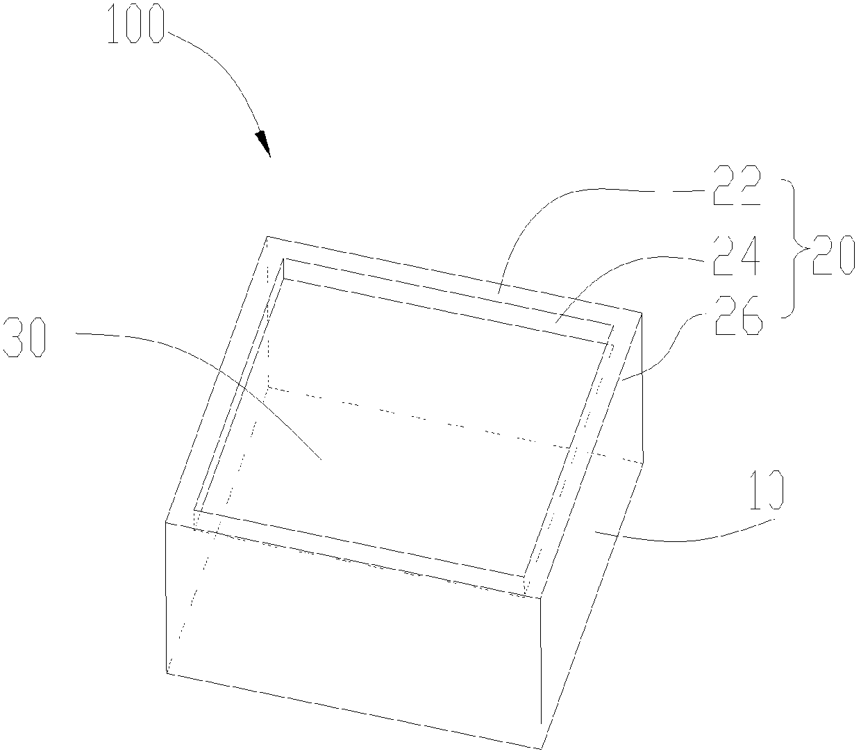
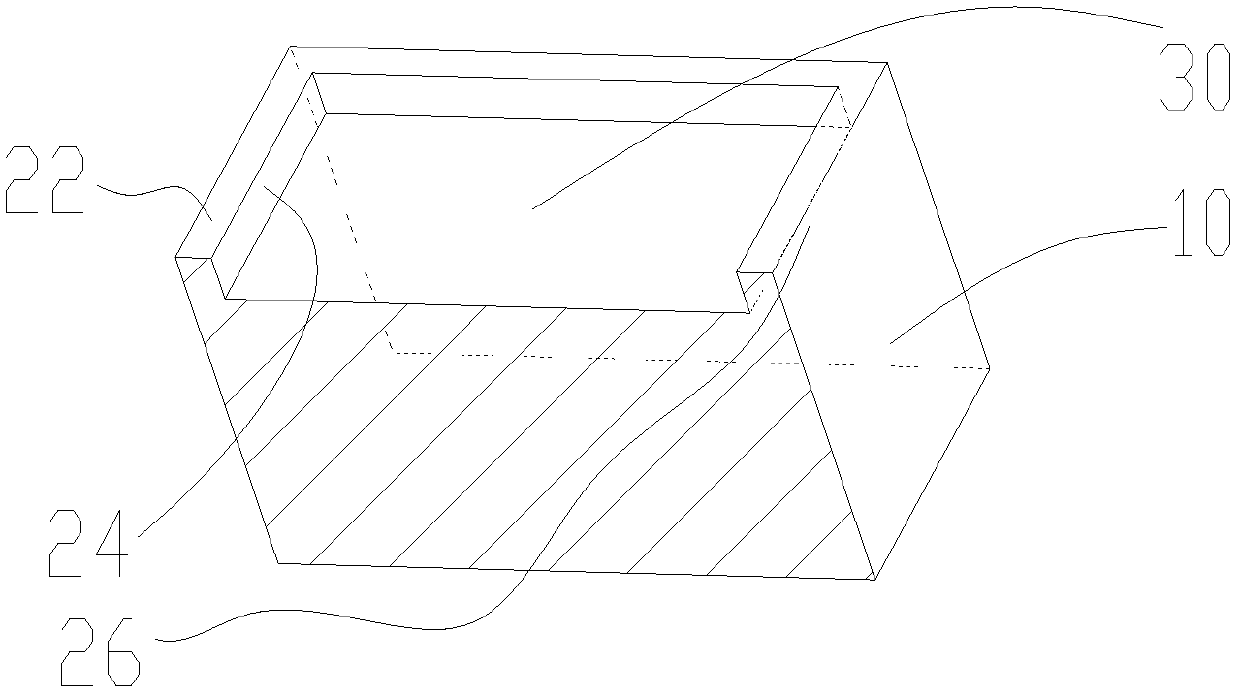
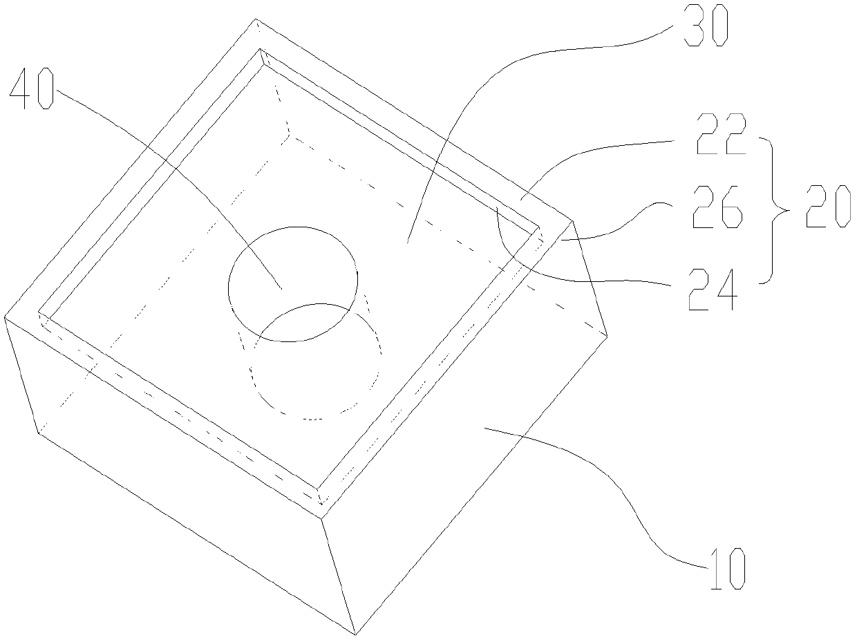
The application provides a dielectric resonator, including a main body and a surrounding wall, the surrounding wall protrudes from one surface of the main body, and the surrounding wall surrounds and forms a cavity area on the surface of the main body, and the surrounding wall makes the cavity area Separated from the outer space of the surrounding wall, the surrounding wall includes a top surface, an inner surface and an outer surface, the inner surface and the outer surface are oppositely arranged and connected between the top surface and the main body , the top surface is located on the surface of the surrounding wall away from the main body, the inner side is the surface of the surrounding wall facing the cavity area, and the outer side faces the outside of the surrounding wall space, the top surface is covered with a metal layer, and the inner and / or outer surfaces are also covered with a metal layer. The application also provides a filter. The dielectric resonator improves the leakage between the open surfaces of the filter, facilitates pushing away the harmonics, and improves the high-frequency suppression performance.

Description

technical field [0001] The present application relates to the technical field of communication, and in particular to a dielectric resonator and a filter including the dielectric resonator. Background technique [0002] As the volume of base station modules becomes smaller and smaller, high-power and high-performance dielectric filters (such as: TEM (transverse electromagnetic) mode dielectric filters, waveguide filled dielectric filters) are more and more widely used in mobile communication equipment. The application of the dielectric filter in the base station, the isolation of the dielectric filter (isolation between the transmitting and receiving channels), assemblability (how the medium is assembled in the base station module), long-term reliability (in high power or harsh environment The reliability used in the base station environment) requirements are getting higher and higher. Only when the design and assemblability of the dielectric filter are continuously improved...

Claims


Application Information

Patent Timeline
Patent Type & Authority Patents(China)
IPC IPC(8): H01P7/10
CPCH01P7/10H01P1/2002H01P1/2053H01P7/04H01P1/2056H01P1/212H05K1/181H05K2201/1006
Inventor 邱莉霞张晓峰刘止愚沈振
Owner HUAWEI TECH CO LTD
Learn More