Al technical title is built by PatSnap Al team. It summarizes the technical point description of the patent document.
An antenna beam and pattern technology, applied in the direction of antennas, electrical components, etc., can solve the problems of slow adaptability, temporary poor, network performance degradation, etc.
Inactive Publication Date: 2017-09-26
TELEFON AB LM ERICSSON (PUBL)
View PDF6 Cites 0 Cited by
Summary
Abstract
Description
Claims
Application Information
AI Technical Summary
This helps you quickly interpret patents by identifying the three key elements:
Problems solved by technology
Method used
Benefits of technology
Problems solved by technology
Tilting the antenna towards the horizon in urban scenarios can lead to degraded network performance e.g. due to high interference to other cells
[0006] However, many algorithms for tuning reconfigurable antennas (such as some SON algorithms) do not consider any orientation as an undesired option
This can lead to unnecessarily slow adaptation and temporarily poor performance during adaptation as these sub-optimal antenna settings are made by automatic algorithms
Method used
Image
Click on the blue label to locate the original text in one second.
Reading with bidirectional positioning of images and text.
Examples
Embodiment Construction
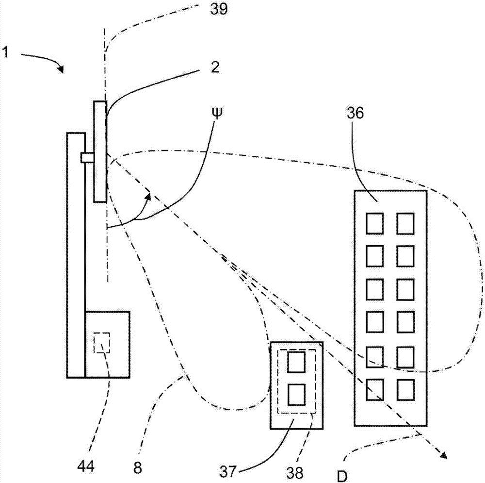
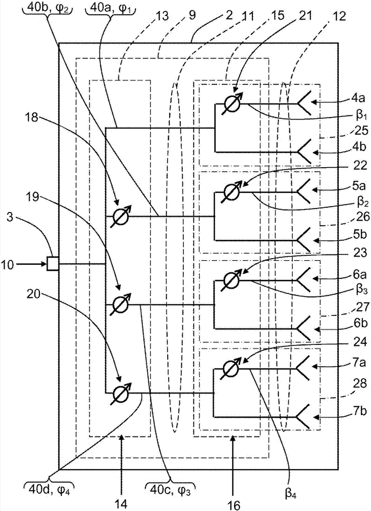
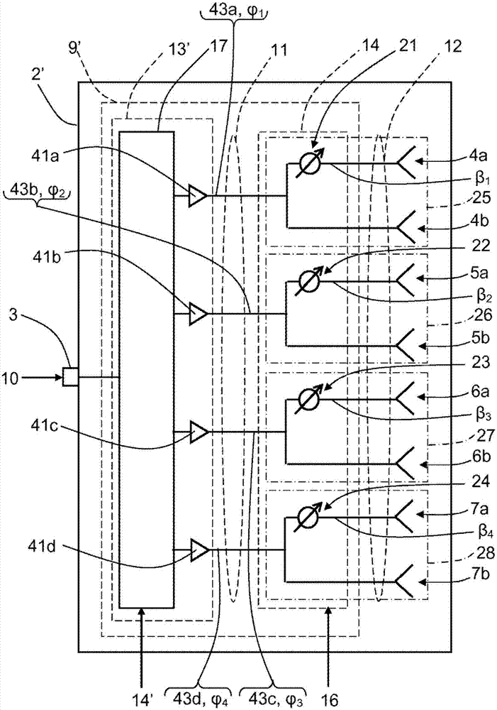
[0026] refer to figure 1 , there is a wireless communication node 1 comprising an antenna arrangement 2 which in this example is part of a Reconfigurable Antenna System (RAS) in a Self Organizing Network (SON). also refer to figure 2 , showing a first example, the antenna device 2 comprises an antenna port 3; eight antenna elements 4a, 4b, 5a, 5b, 6a, 6b, 7a, 7b arranged to provide an antenna beam pattern 8; Port 3 receives at least one phase control device 9 of an input signal 10 . The antenna arrangement 2 comprises four sub-arrays 25, 26, 27, 28, wherein each sub-array 25, 26, 27, 28 comprises two antenna elements 4a, 4b; 5a, 5b; 6a, 6b; 7a, 7b.
[0027] In order to tune the RAS settings, the phase control means 9 is arranged to determine the four corresponding phase shifts by the input signal 10 The first set of phase shifts is formed to determine the four intermediate signal components 11 from the input signal 10 . To this end, the phase control device 9 includes: a...
PUM
Abstract
The present disclosure relates to a wireless communication node (1) comprising at least one antenna arrangement (2, 2', 2"). Each antenna arrangement (2, 2', 2") comprises at least one antenna port (3), at least two antenna elements (4a, 4b, 5a, 5b, 6a, 6b, 7a, 7b) arranged for providing an antenna beam pattern (8), and a phase control arrangement (9, 9', 9") arranged to receive at least one input signal (10) via said antenna port (3) and to determine a plurality of intermediate signal components (11) from said input signal (10) by determining a first set of respective phase shifts (Phi 1, Phi 2, 10 Phi 3, Phi 4; Theta 1, Theta 2, Theta 3, Theta 4, Theta 5, Theta 6, Theta 7, Theta 8) for said input signal (3). The phase control arrangement (9) is further arranged to determine a final signal component (12) for each antenna element (4a, 4b, 5a, 5b, 6a, 6b, 7a, 7b) from said intermediate signal components (12) by determining a second set of respective phase shifts (beta 1, beta 2, beta 3, beta 4; Phi 1, Phi 2, Phi 3, Phi 4, Phi 5, Phi 6, Phi 7, Phi 8) for said intermediate signal components (12), wherein the second set of phase shifts (beta 1, beta 2, beta 3, beta 4; Phi 1, Phi 2, Phi 3, Phi 4, Phi 5, Phi 6, Phi 7, Phi 8) is arranged to provide a lowered gain of the antenna arrangement (2, 2', 2") in at least one direction (D). The present disclosure also relates to a corresponding method.
Description
technical field [0001] The present disclosure relates to wireless communication systems, and in particular, to controlling an antenna beam pattern of an antenna arrangement having at least two antenna elements. Background technique [0002] Future cellular networks are expected to be able to deliver high data rates up to several gigabytes per second while being energy efficient. One possible way to achieve such high data rates and / or reduce energy consumption in cellular networks is to deploy a reconfigurable antenna system (RAS) or multiple reconfigurable antenna systems. RAS is an antenna system whose radiation characteristics can be changed by the network after deployment and adapted eg to current traffic requirements. [0003] The most common antenna parameter that can be controlled remotely is antenna tilt. More possibilities for modifying the shape of the antenna lobe besides one-dimensional tilt will be introduced, which will open up new possibilities for improving ...
Claims
Application Information
Patent Timeline
Application Date:The date an application was filed.
Publication Date:The date a patent or application was officially published.
First Publication Date:The earliest publication date of a patent with the same application number.
Issue Date:Publication date of the patent grant document.
PCT Entry Date:The Entry date of PCT National Phase.
Estimated Expiry Date:The statutory expiry date of a patent right according to the Patent Law, and it is the longest term of protection that the patent right can achieve without the termination of the patent right due to other reasons(Term extension factor has been taken into account ).
Invalid Date:Actual expiry date is based on effective date or publication date of legal transaction data of invalid patent.