Bearing ring taking-out device for casting

A technology for taking out a device and a bearing ring, applied in the field of mechanical equipment, can solve the problems of high temperature of the bearing ring, poor grasping of the hooking tool and the bearing ring, and falling of workers.

Active Publication Date: 2017-09-29
ANHUI HAILI PRECISION CASTING CO LTD
View PDF7 Cites 3 Cited by
  • Summary
  • Abstract
  • Description
  • Claims
  • Application Information

AI Technical Summary

Problems solved by technology

[0002] For large bearings, the inner and outer rings are mostly produced by centrifugal casting. After the bearing ring is cast, workers usually use hooking and knocking to pull out the bearing ring assembly. During the pulling process, due to Workers use too much force and the hooking tool is not firmly connected with the bearing ri

Method used


Image

  • Bearing ring taking-out device for casting
  • Bearing ring taking-out device for casting
  • Bearing ring taking-out device for casting

Examples


Embodiment Construction

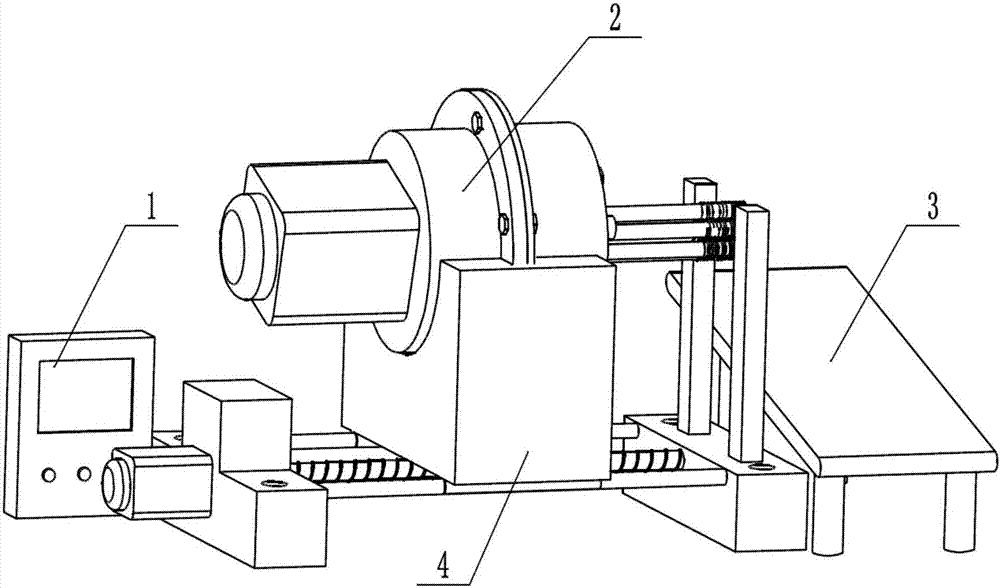
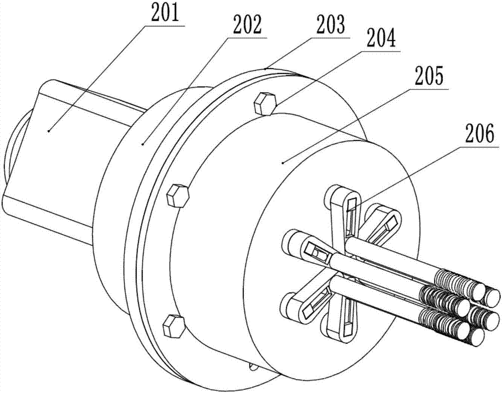
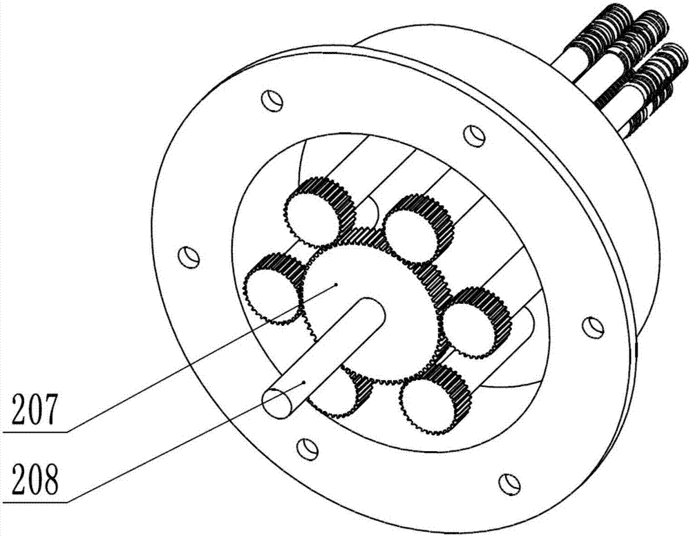
[0017] A bearing ring removal device for casting is composed of a controller 1, a tensioning mechanism 2, a sliding plate 3 and a displacement mechanism 4. The tensioning mechanism 2 includes a tensioning motor 201, a rear shell 202, a flange 203, Flange bolt 204, front shell 205, pull rod mechanism 206, large gear 207 and main shaft 208, described stretching motor 201 is fixedly installed on the rear shell 202, and the end that described front shell 205 and rear shell 202 contacts all is provided with Flange 203, the flange 203 on the front shell 205 and the rear shell 202 is connected and fixed by flange bolts 204, the front shell 205 is provided with a pull rod mechanism 206, and the middle position in the cavity of the front shell 205 is provided with The large gear 207, the large gear 207 is installed on the main shaft 208, the main shaft 208 is keyed to the output shaft of the tension motor 201 through a coupling, the lower end of the front shell 205 and the lower end of ...


PUM


Abstract

A bearing ring taking-out device for casting comprises a controller, a tight supporting mechanism, a sliding-off plate and a displacement mechanism. The tight supporting mechanism is fixed to the upper end of the displacement mechanism. The sliding-off plate is arranged on the right side of the displacement mechanism. The controller and the tight supporting mechanism are electrically connected with the displacement mechanism. Through the displacement mechanism, stable displacement of the tight supporting mechanism is achieved. The tight supporting mechanism opens a plurality of pull rod mechanisms through meshing of large gears on a tight supporting motor spindle and small gears on the pull rod mechanisms, then radial force is applied to the inner wall of a bearing ring. Friction force is increased through friction stripes at the ends of the pull rod mechanisms, thus the bearing ring can be pull out smoothly, the pull rod mechanisms comprise locating bolts and locating grooves, the rotation radius of the pull rod mechanisms can be adjusted, the universality of the bearing ring taking-out device is improved, and production cost is lowered. Through arrangement of a sliding table, manual contact with the bearing ring under high temperature is avoided, and thus the bearing ring rolls to a fixed area under guiding of a slope of the sliding table.

Description

technical field [0001] The invention relates to a device for taking out a bearing ring for casting. Specifically, it adopts a tightening mechanism and a displacement mechanism. After use, the device for taking out a bearing ring for casting can replace manual removal of the casting bearing ring, and belongs to the field of mechanical equipment. Background technique [0002] For large bearings, the inner and outer rings are usually produced by centrifugal casting. After the bearing ring is cast, workers usually use hooking and knocking to pull out the bearing ring assembly. During the pulling process, due to Workers use too much force and the hooking tool is not firmly connected with the bearing ring, which can easily cause the worker to fall, and the temperature of the newly cast bearing ring is extremely high. After the worker directly hooks the bearing ring, it is easy to cause various accidents due to improper operation. Accident, but, also do not have a kind of correspon...

Claims


Application Information

Patent Timeline
IPC IPC(8): B22D13/10
CPCB22D13/108
Inventor 范国隆于复生范国良
Owner ANHUI HAILI PRECISION CASTING CO LTD
Why Eureka
Try Eureka