
Novel automatic-closing-preventing antitheft door

An automatic closing and anti-theft door technology, which is applied in the field of anti-theft doors, can solve the problems of time-consuming, labor-intensive and expensive, unable to solve problems such as forgetting to bring keys, not carrying keys with you, and achieve the effect of ensuring life safety

Inactive Publication Date: 2017-09-29
台山平安五金制品有限公司
View PDF8 Cites 2 Cited by
  • Summary
  • Abstract
  • Description
  • Claims
  • Application Information

AI Technical Summary

Problems solved by technology

[0004] At present, with the continuous innovation of anti-theft technology, the safety protection performance of anti-theft doors has been greatly improved. However, as the safety protection level of anti-theft doors is getting higher and higher, the inconvenience caused to users is also More and more, such as accidentally closing the anti-theft door when going out to see off guests, or the anti-theft door is closed by the wind, but it is found that there is no key with it, and for example, the elderly tend to forget to carry the key when they go out.
Although this situation is not common, once it happens, it will inevitably cause many unnecessary troubles
Especially in view of the good safety protection performance of the existing anti-theft door, the user cannot solve the problem of how to open the door if he forgets to bring the key. He can only ask a professional unlocker to open the door, but even this is very time-consuming, laborious and expensive.
[0005] In addition, the existing anti-theft door exterior doors generally have a certain fire prevention function, but if a fire occurs in the surrounding environment, it is difficult for the user to find it at home at the first time. lives in great danger

Method used


Image

  • Novel automatic-closing-preventing antitheft door
  • Novel automatic-closing-preventing antitheft door
  • Novel automatic-closing-preventing antitheft door

Examples


Embodiment Construction

[0020] To further illustrate the various embodiments, the present invention is provided with accompanying drawings. These drawings are a part of the disclosure of the present invention, which are mainly used to illustrate the embodiments, and can be combined with related descriptions in the specification to explain the operating principles of the embodiments. With reference to these contents, those skilled in the art should understand other possible implementations and advantages of the present invention.

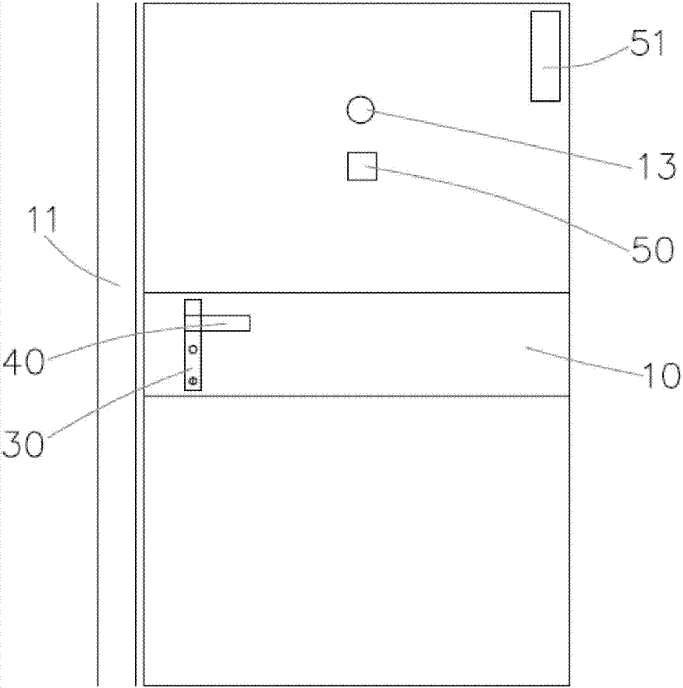
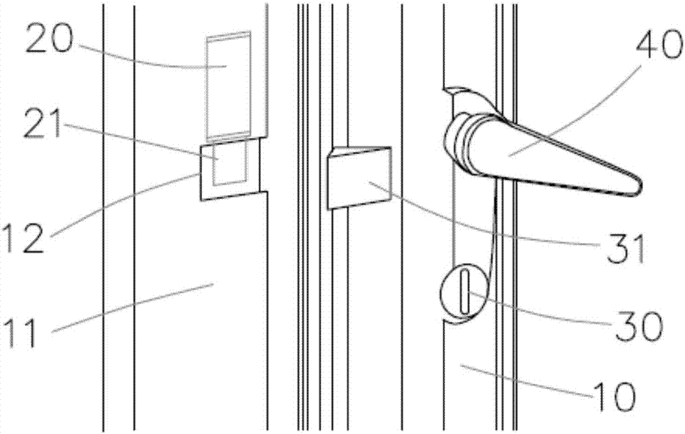
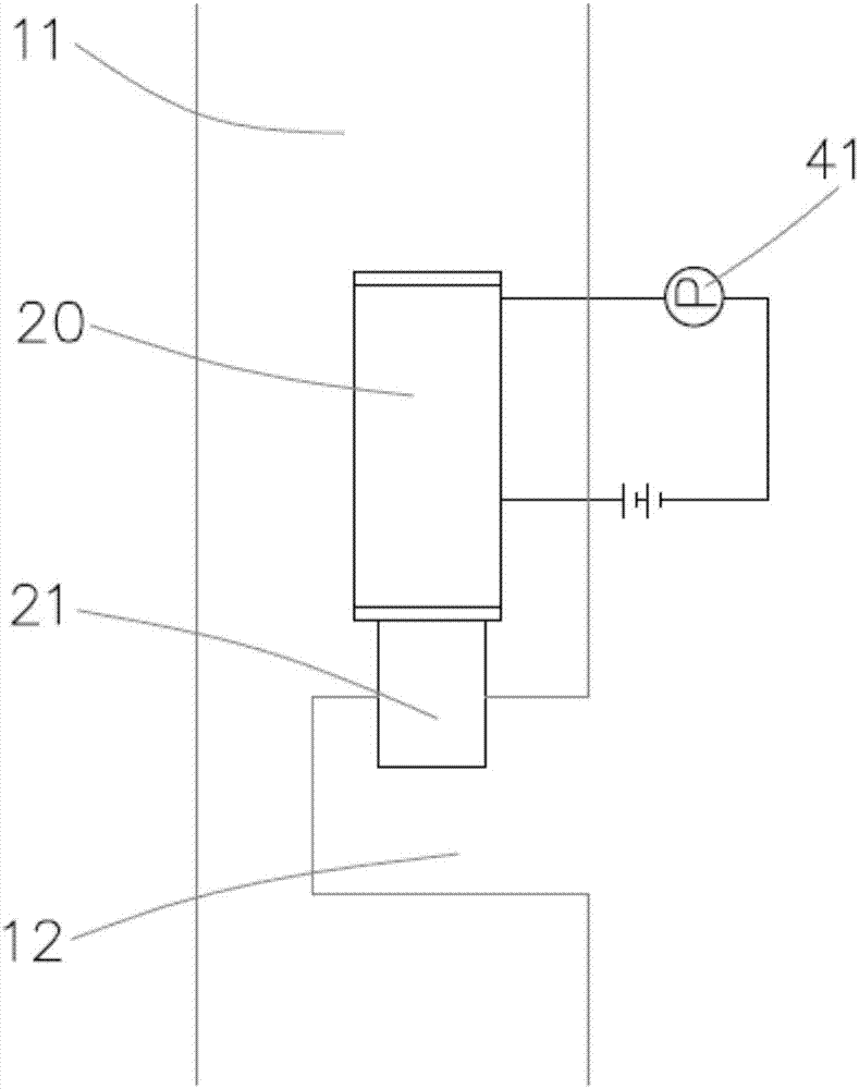
[0021] Please also see figure 1 , figure 2 , image 3 , Figure 4 as well as Figure 5 ,in, figure 1 It is a structural schematic diagram of the novel anti-automatic closing anti-theft door of the present invention; figure 2 It is a partially enlarged view of the novel anti-automatic closing anti-theft door of the present invention; image 3 It is a structural schematic diagram of the electric push rod of the present invention; Figure 4 It is the working principl...


PUM


Abstract

The invention relates to a novel automatic-closing-preventing antitheft door. The novel automatic-closing-preventing antitheft door comprises an antitheft door main body, a door lock, a pressure sensor, a power supply, an alarming mechanism and an electric push rod, wherein the door lock, the pressure sensor, the power supply and the alarming mechanism are arranged on the antitheft door main body; the electric push rod is arranged on a door frame; the door lock is connected with an outer handle through a rotating mechanism; the pressure sensor is arranged on the outer handle; a groove is formed in the door frame and is opposite to a bolt of the door lock; a retractable rod of the electric push rod is retractably mounted in the groove; and the electric push rod, the pressure sensor and the power supply form a series loop. When an external force acts on the outer handle, the pressure sensor converts pressure into current, and therefore, the retractable rod of the electric push rod is separated from the groove. The novel automatic-closing-preventing antitheft door is simple and reasonable in structure, automatic closing of the antitheft door can be prevented effectively, and therefore, the effect of reminding a user to carry a key when the user goes out is achieved.

Description

technical field [0001] The invention relates to the technical field of anti-theft equipment, in particular to a novel anti-theft automatic closing anti-theft door. Background technique [0002] The anti-theft safety door refers to a door equipped with an anti-theft lock, which can resist abnormal opening under certain conditions within a certain period of time, has certain safety protection performance and meets the corresponding anti-theft safety level. It is an important guarantee for home protection devices. [0003] A generally qualified anti-theft door cannot be pried open by ordinary hand tools such as chisels, screwdrivers, crowbars, and portable electric tools such as electric drills within 15 minutes, or an opening of 615 square millimeters can be opened on the door leaf, or 150 square millimeters at the locking point. Open an opening of 38 mm2 in the semicircle of . [0004] At present, with the continuous innovation of anti-theft technology, the safety protection...

Claims


Application Information

Patent Timeline
Patent Type & Authority Applications(China)
IPC IPC(8): E06B5/11E06B5/16E06B7/30E06B7/28E05B3/00E05F5/02G08B17/06
CPCE06B5/11E05B3/00E05F5/02E06B5/16E06B7/28E06B7/30G08B17/06
Inventor 蔡志伟
Owner 台山平安五金制品有限公司
Learn More