Mechanical sealing structure with end face being provided with vein-shaped grooves

A mechanical seal and blade vein technology, which is applied to engine seals, mechanical equipment, engine components, etc., can solve problems such as large leakage, seal failure, and poor chip removal ability, so as to improve the hydrodynamic pressure effect, prolong the service life, The effect of improving work efficiency

Active Publication Date: 2017-09-29
BEIHANG UNIV
View PDF6 Cites 13 Cited by
  • Summary
  • Abstract
  • Description
  • Claims
  • Application Information

AI Technical Summary

Problems solved by technology

The failure of a stable liquid film between the end faces of traditional contact mechanical seals, the wear of the end faces, and the thermal cracking of the sealing ring are all likely to lead to the failure of the seal.
The current non-contact seals are mainly modified on the end faces of the dynamic and static rings (deep groove type, shallow groove type and textured configuration). These structures have improved the performance of the mechanical seal to a certain extent, but there are still some Disadvantages: Although the deep groove type has low frictional energy consumption and strong end face opening ability, the leakage is greater than that of ordinary end face mechanical seals of the same specification
At the same time, the performance of chip removal during work is poor, which should cause the accumulation of particles; various textures have compression resistance, insufficient fluid film thickness between end faces, or insufficient fluid film rigidity to resist external interference, resulting in abnormal sealing system Stable operation, but also has the problem of poor chip removal ability

Method used


Image

  • Mechanical sealing structure with end face being provided with vein-shaped grooves
  • Mechanical sealing structure with end face being provided with vein-shaped grooves
  • Mechanical sealing structure with end face being provided with vein-shaped grooves

Examples


Embodiment Construction

[0035] The present invention will be described in detail below with reference to the drawings and specific embodiments.

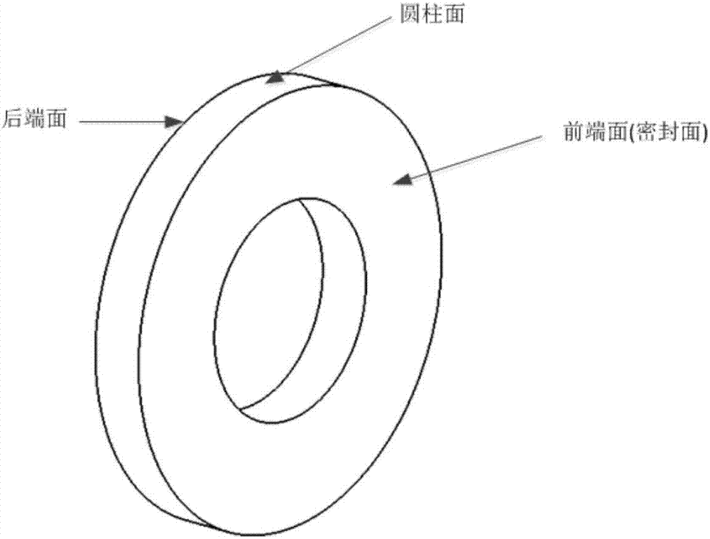
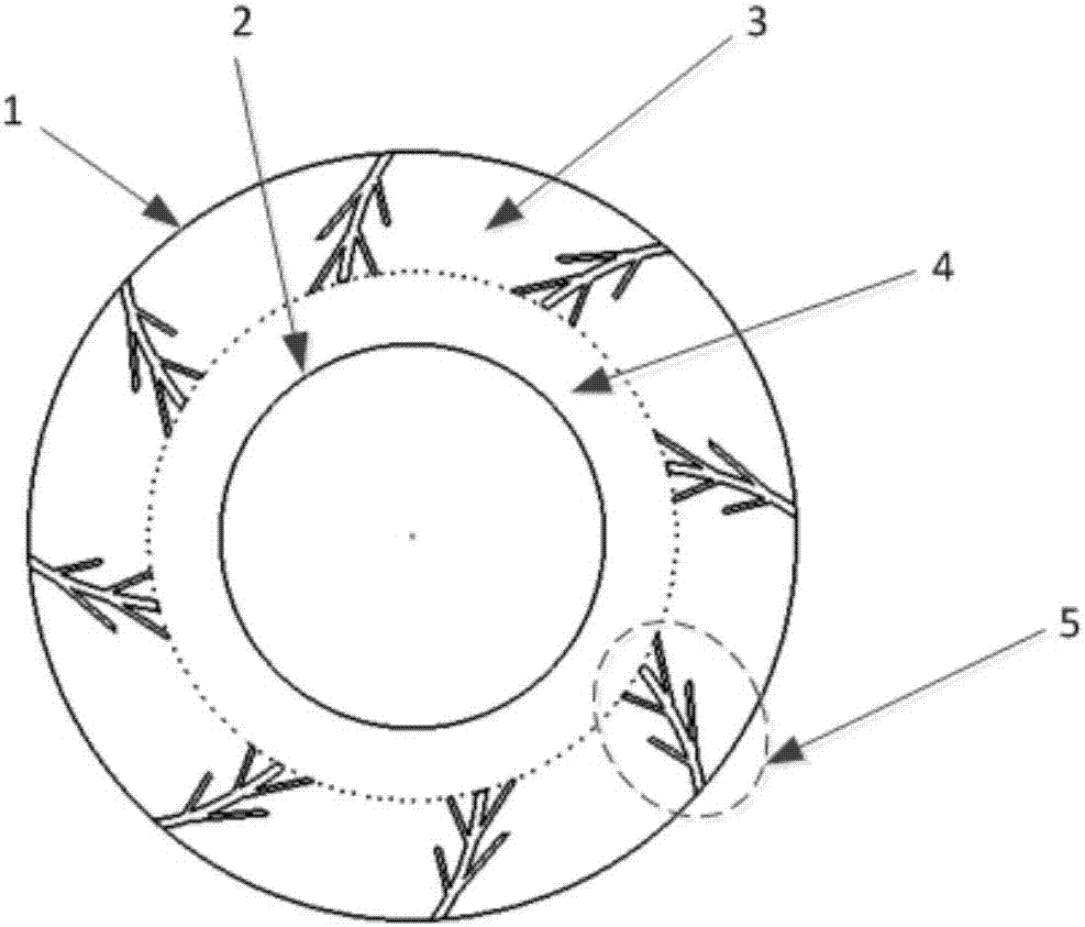
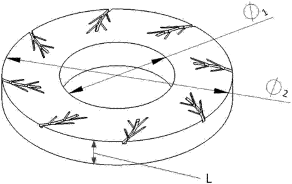
[0036] The structure of the embodiment of the present invention is as Figure 1 ~ Figure 6 Shown. It includes an outer ring (1), an inner ring (2), a sealing weir area (3), a sealing dam area (4), and a vein-shaped groove (5). Such as figure 2 As shown, they are all located at different positions on the front face (seal surface) of the mechanical seal structure. The inner diameter of the entire mechanical seal structure is The outer diameter is The axial thickness of the mechanical seal structure is L. The front end surface (seal surface) of the mechanical seal structure is provided with 8 vein-shaped grooves (5), the number of which varies with the size of the mechanical seal structure, and each vein-shaped groove is symmetrical about the axis of the mechanical seal structure. The vein-shaped groove (5) includes a first branch groove (51), a second bran...


PUM


Abstract

The invention discloses a mechanical sealing structure with the end face being provided with vein-shaped grooves. The front end face, namely the sealing face, of the mechanical sealing structure is composed of an outer ring (1), an inner ring (2), a sealing weir area (3), a sealing dam area (4) and the 6-12 vein-shaped grooves (5) which are all located in the different positions of the front end face, namely the sealing face, of the mechanical sealing structure. The number of the vein-shaped grooves (5) is changed along with the size of the mechanical sealing structure. Each vein-shaped groove (5) is composed of a first branch groove body (51), a second branch groove body (52), a third branch groove body (54), a fourth branch groove body (55) and a main groove body (53). The hydrodynamic pressure effect is effectively improved, the side effect caused by unevenness of the mechanical sealing end face is reduced, and the working efficacy of mechanical sealing is improved; and the rub-impact failure under the extreme working conditions of the small film thickness and the small pressure difference can be effectively avoided, non-contact sealing is achieved, abrasion resistance is improved, the service life is prolonged, and sealing reliability is improved.

Description

Technical field [0001] The invention provides a mechanical seal structure with vein-shaped grooves on the end surface, specifically, a certain number of vein-shaped grooves are provided on the end surface of a moving ring or a static ring, which belongs to the rotary shaft seal in the fluid seal Technical field. Background technique [0002] Mechanical seal is an axial end face sealing device that relies on the pre-tensioning of the dynamic and static ring end face seal pairs by elastic elements and the compaction of medium pressure and elastic element pressure to achieve sealing, so it is also called end face seal. Mechanical seals are widely used in equipment such as centrifugal pumps, centrifuges, reactors and compressors. With the rapid development of the industrial field, practical applications require mechanical seals to adapt to more extreme working conditions such as high pressure, high speed, and abrupt conditions, which puts forward higher requirements on the performan...

Claims


Application Information

Patent Timeline
Patent Type & Authority Applications(China)
IPC IPC(8): F16J15/34F16J15/40
CPCF16J15/3408F16J15/40
Inventor 寇桂岳王岩李兴虎石谦
Owner BEIHANG UNIV
Why Eureka
Try Eureka