Mechanical seal end face structure of imitated grinding disc texture

A mechanical seal and end face technology, applied in the direction of engine seals, mechanical equipment, engine components, etc., can solve the problems of limited end face fluid film bearing capacity, poor start-stop effect, short seal life, etc., to extend life, reduce leakage, The effect of reducing end-face contact wear

Pending Publication Date: 2017-11-03
ZHEJIANG UNIV OF TECH
View PDF15 Cites 1 Cited by
  • Summary
  • Abstract
  • Description
  • Claims
  • Application Information

AI Technical Summary

Problems solved by technology

[0003] In order to overcome the shortcomings of short seal life, poor start-stop effect and limited bearing capacity of the fluid film on the end face mechanical seal structure, the present invention

Method used


Image

  • Mechanical seal end face structure of imitated grinding disc texture
  • Mechanical seal end face structure of imitated grinding disc texture
  • Mechanical seal end face structure of imitated grinding disc texture

Examples


Embodiment 1

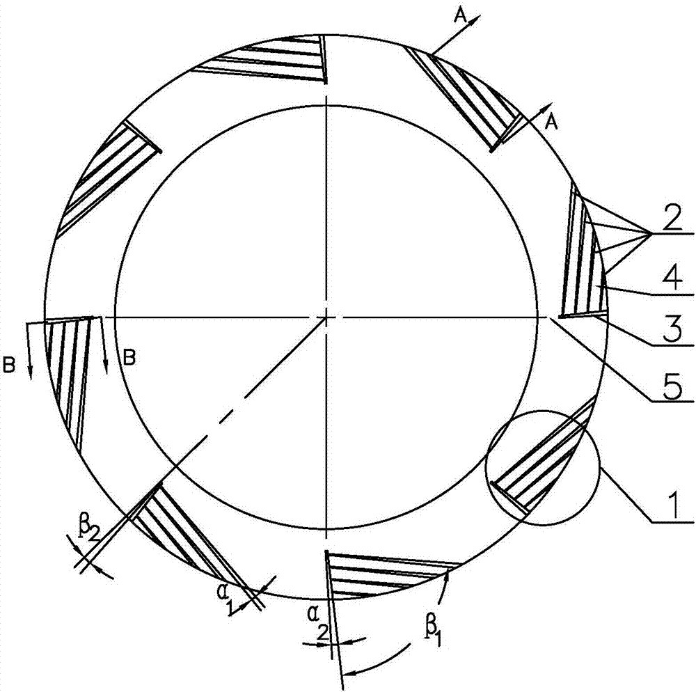
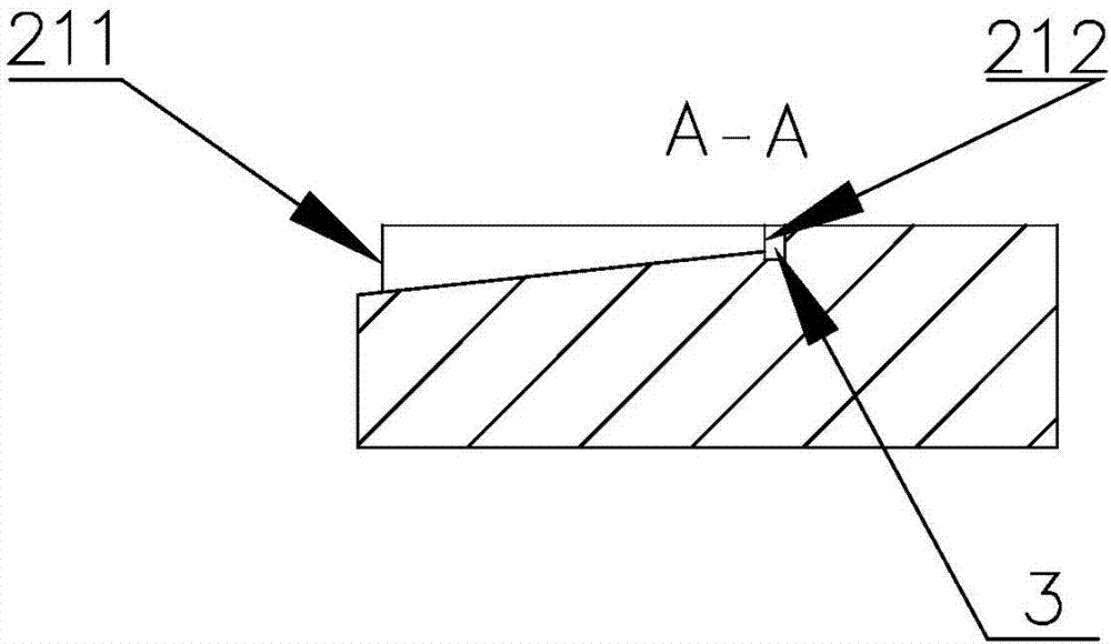
[0021] Reference Figure 1 ~ Figure 4 , A mechanical seal end surface structure that imitates the texture of a grinding disc, comprising a moving ring and a static ring of the mechanical seal. One side of the end surface of the moving ring and the static ring is the high pressure side, that is, upstream. The other side is the low pressure side, that is downstream; the end surface of at least one of the moving ring and the static ring is provided with a plurality of streamlined grooves 1 that are evenly distributed along the circumferential direction, imitating the surface texture of the grinding disc; the streamlined grooves are moved by the base The pressure groove 2 and the diversion groove 3 are composed of gradually narrowing from upstream to downstream, and the depth becomes shallower. The basic dynamic pressure grooves are multi-row parallel, and the grooves are separated by a sealing weir 4 of equal depth; The diversion groove penetrates through each basic dynamic pressur...

Embodiment 2

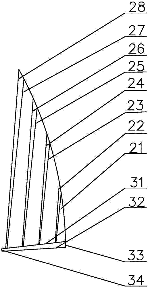
[0028] Reference Figure 5 The difference between this embodiment and embodiment 1 is that there are multiple sections of diversion grooves 6 in the streamlined groove, the number of diversion grooves is equal to the basic dynamic pressure grooves, and the basic dynamic pressure grooves are connected to each other, and each section of the guide The flow troughs all present a convergent structure with deep upstream and shallow downstream. Refer to Example 1 for the specific depth range. The left and right side walls of the diversion groove are flat, and the included angle range can refer to Example 1. The upstream and downstream width of the diversion groove is equal to the distance between the basic dynamic pressure grooves. This kind of groove type can generate high pressure zone near the diversion groove area. Due to the different positions of diversion grooves, it can enhance the dynamic pressure effect on the overall end surface, improve the fluid film rigidity, thereby redu...


PUM


Abstract

A mechanical seal end face structure of imitated grinding disc texture comprises a movable ring and a fixed ring which are in mechanical seal; one side of each of the movable ring and the fixed ring serves as the high-pressure side, that is the upstream side, the other side of each of the movable ring and the fixed ring is the low-pressure side, that is the downstream side, multiple streamline grooves of the imitated grinding disc surface texture are evenly distributed in the end face of at least one seal ring of each of the movable ring and the fixed ring in the circumferential direction, composed of foundation movable pressure grooves and flow guide grooves, and gradually narrowed from upstream to downstream and become shallow in depth; the foundation movable pressure groove are arranged in parallel in a multi-row manner, and the grooves are partitioned by sealing weirs with the equal depth; the flow guide grooves penetrates the foundation movable pressure grooves, and seal dams are arranged on the downstream portions of the streamline grooves; through the convergent structure of the imitated grinding disc texture, the higher flow guide effect is achieved, and leakage is reduced while the end fluid movable pressure effect is improved.

Description

Technical field [0001] The invention belongs to the technical field of end face mechanical seal structure design, and particularly relates to a deep end face seal structure compounded by a diversion groove and a plurality of basic dynamic pressure grooves, which is suitable for shaft ends of various industrial pumps, kettles and other rotating machinery. Seal transposition, suitable for liquid lubricated mechanical seals with medium and low speeds. Background technique [0002] Mechanical seal is the most commonly used rotary shaft seal in fluid machinery. Because of its good sealing performance, less leakage, and relatively low frictional power consumption, it has been widely used in various chemical equipment, but because it has a pair of direct contact Friction of the end face results in a short life span, especially under harsh conditions such as high temperature and high pressure. In order to prolong the life of ordinary mechanical seals, people have developed a way to impr...

Claims


Application Information

Patent Timeline
IPC IPC(8): F16J15/34
CPCF16J15/34
Inventor 孟祥铠陈文杰王玉明梁杨杨沈明学彭旭东
Owner ZHEJIANG UNIV OF TECH
Why Eureka
Try Eureka