Micro-hole end face mechanical seal structure with air inlet grooves

A technology of end face mechanical seal and air intake groove, which is applied in the direction of engine seal, mechanical equipment, engine components, etc., can solve the problems of weakened end face dynamic pressure effect and difficult entry of sealing medium, so as to improve opening performance, stability, Effect of enhancing dynamic pressure effect and anti-disturbance

Inactive Publication Date: 2013-12-25
ZHEJIANG UNIV OF TECH
View PDF12 Cites 3 Cited by
  • Summary
  • Abstract
  • Description
  • Claims
  • Application Information

AI Technical Summary

Problems solved by technology

[0003] In order to solve the problem that the non-contact dry gas seal is difficult for the sealing medium to enter the sealing end face under high-pressure frequent start-stop conditions and the end-face dynamic pressure effect is weakened due to the negative pressure effect in the hole area under high-speed working conditions, the present invention provides a high-pressure dry gas seal. Frequent start and stop, high speed and solid particles, etc., improve the opening problem of the sealing end face, and improve the dynamic pressure effect of the end face mechanical seal structure with air inlet groove microporous end face

Method used


Image

  • Micro-hole end face mechanical seal structure with air inlet grooves
  • Micro-hole end face mechanical seal structure with air inlet grooves
  • Micro-hole end face mechanical seal structure with air inlet grooves

Examples


Embodiment 1

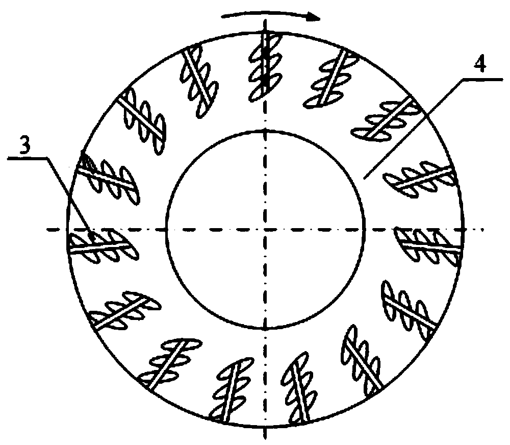
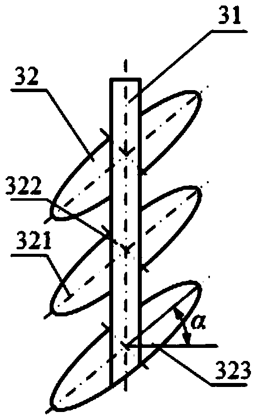
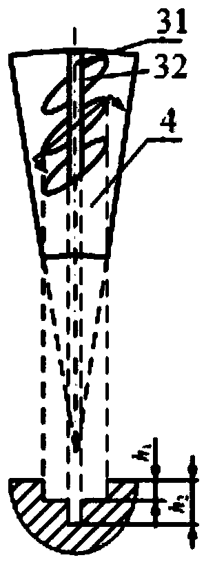
[0019] Embodiment 1 The microporous end face mechanical seal structure with air inlet grooves of the present invention includes two end faces for mechanical sealing, namely the moving ring 1 and the static ring 2, and one of the end faces is from the high pressure side to the low pressure side Micropore groups 3 and annular sealing dams 4 are arranged in sequence according to the symmetrical distribution of the center of rotation; multiple columns of micropore groups 3 are distributed on the high-pressure side of the end surface, and the micropore groups 3 include linear air inlet grooves 31 and a plurality of Oval micropore 32, the center of described micropore 32 is positioned on described air inlet groove 31, and the long axis of each microhole 32 is identical with the included angle of air inlet groove 31, and described microhole 32 faces One end of the airflow is located on the high-pressure side of the end face; the straight line where the air inlet groove 31 is located i...


PUM


Abstract

A micro-hole end face mechanical seal structure with air inlet grooves comprises two end faces for mechanical sealing, namely a moving ring and a stationary ring, wherein one end face is sequentially provided with micro-hole groups and annular sealing dams which are symmetrically distributed relative to the rotation center from the high-pressure side to the low-pressure side. Multiple rows of micro-hole groups are distributed on the high-pressure side of the end face and comprise the linear air inlet grooves and multiple elliptic micro-holes, the centers of the micro-holes are located on the air inlet grooves, included angles formed by long shafts of the micro-holes and the air inlet grooves are identical, and one end of each micro-hole facing air flows is located on the high-pressure side of the end face. A straight line where the air inlet grooves are located is located on the radius of the end face. The low-pressure side of the end face is provided with the annular sealing dams with smooth faces. The micro-hole end face mechanical seal structure has the advantages that the opening performance under the high-pressure frequent start-stop condition is improved; the problem of poor hydrodynamic effect of the end faces caused by the air negative pressure effect is solved; the solid particle preventing capacity and the advantages of the micro-holes are fully played; the hydrodynamic effect and the disturbance-resisting performance are enhanced, the service life is prolonged, and the stability of the end faces is improved.

Description

technical field [0001] The invention relates to a microporous end face mechanical seal structure with an air inlet groove. Background technique [0002] Due to the excellent anti-friction performance of the microporous end face and its excellent tribological properties in the occasions where it is easy to gasify and crystallize, and the content of solid particles is high, it is widely used. At home and abroad, there are various microporous sealing end surface structures such as circular micropores, directional micropores, double-row inclined directional micropores, variable distribution micropores, spike-shaped micropores, and spiral groove auxiliary micropores, so as to fully Utilize the anti-solid particle ability of the microporous structure, improve its dynamic pressure effect, and prolong the service life of the sealing end face. However, under high-pressure conditions where the machine starts and stops frequently, the gas is not easy to enter the closed hole area, res...

Claims


Application Information

Patent Timeline
Patent Type & Authority Applications(China)
IPC IPC(8): F16J15/34
Inventor 白少先马春红彭旭东孟祥铠
Owner ZHEJIANG UNIV OF TECH
Why Eureka
Try Eureka