Novel LED lamp

An LED lamp, a new type of technology, applied in the field of lighting, can solve the problems of causing accidents, long time consumption, low work efficiency, etc., and achieve the effect of improving firmness and simplicity, improving installation speed, and reducing operation steps.

Active Publication Date: 2017-09-29
HANCON LIGHTING CO LTD ZHUHAI
View PDF3 Cites 3 Cited by
  • Summary
  • Abstract
  • Description
  • Claims
  • Application Information

AI Technical Summary

Problems solved by technology

Most of the LED lighting fixtures in the prior art do not have an electric shock protection structure. When the user replaces the lamp cap or repairs the lamp, it is easy to touch the contacts in the lamp cap holder, which will cause electric shock, cause accidents, and cause personal and property losses. , At the same time, the existing LED lighting fixtures are generally fixedly connected together by fasteners such as screws. When installing, it is necessary to use tools such as a screwdriver to install the lamp holder and the lamp holder together; when the LED lighting fixture fails, it is necessary to use a screwdriver, etc. The tool disassembles the lamp holder and the lamp holder, resulting in long time-consuming installation and disassembly, low work efficiency, and cannot meet the existing needs

Method used


Image

  • Novel LED lamp
  • Novel LED lamp
  • Novel LED lamp

Examples


Embodiment Construction

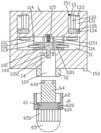
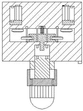
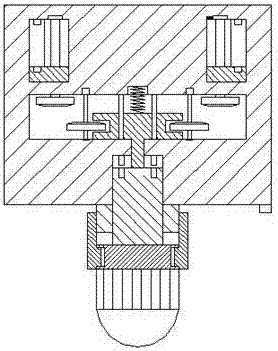
[0021] Such as Figure 1-Figure 6 As shown, a new type of LED lamp of the present invention includes a lamp holder 1 and a lamp cap 6 cooperating with the lamp holder 1 described above. 12 is provided with a through groove 120, the socket 1 is provided in the lamp socket 1 on the rear side of the through groove 120, and the inner wall of the rear side of the socket 14 is provided with a second post 140, and the rear of the socket 14 The lamp holder 1 is provided with a first receiving cavity 11, the rear inner wall of the first receiving cavity 11 is provided with a counterbore 115, and the first receiving cavity 11 on the front side of the counterbore 115 is provided with a pushing A block 110, a tension spring 1151 is provided between the rear end surface of the push block 110 and the counterbore 115, and guide rods 116 are provided in the first accommodation cavity 11 on both sides of the tension spring 1151. The guide rod 116 is slidably connected with the push block 110....


PUM


Abstract

The invention discloses a novel LED lamp. The novel LED lamp comprises a lamp holder and a lamp head in matched connection with the lamp holder, wherein an external spiral thread piece is arranged on the front end surface of the lamp holder; a through groove is formed in the external spiral thread piece; an insertion hole is formed at the position, on the rear side of the through groove, in the lamp holder; a second insertion column is arranged on the inner wall of the rear side of the insertion hole; a first accommodating cavity is formed at the position, behind the insertion hole, in the lamp holder; a counter bore is formed in the inner wall of the rear side of the first accommodating cavity; a push block is arranged at the position, in the front side of the counter bore, in the first accommodating cavity; a tension spring is arranged between the end surface of the rear side of the push block and the counter bore; guide rods are symmetrically arranged at the positions, on the two sides of the tension spring, in the first accommodating cavity and are in sliding matched connection with the push block; an ejection rod penetrating the inner wall body of the lamp holder and extending into the insertion hole is arranged on the front end side of the push block; concave holes are formed in the end walls of the left side and the right side of the push block; spline revolving shafts are symmetrically arranged at the positions, in the outer side of the push block, in the first accommodating cavity; the rear side ends of the spline revolving shafts are connected with driving machines. The novel LED lamp is simple in structure, simple and convenient to mount and firm in connection and has an anti-electric shock function, so that electric shock accidents are prevented, and mounting efficiency and power supply safety are improved.

Description

technical field [0001] The invention relates to the technical field of lighting, in particular to a novel LED lamp. Background technique [0002] At present, LED is widely used in life, especially in the field of lighting technology, and innovative products are constantly being supplied to the market. LED lights have the characteristics of environmental protection, no pollution, low power consumption, high luminous efficiency, and long life. Therefore, LED lights will become the best choice for current energy-saving renovations. Most of the LED lighting fixtures in the prior art do not have an electric shock protection structure. When the user replaces the lamp cap or repairs the lamp, it is easy to touch the contacts in the lamp cap holder, which will cause electric shock, cause accidents, and cause personal and property losses. At the same time, the existing LED lighting fixtures are generally fixedly connected together by fasteners such as screws. When installing, it is ...

Claims


Application Information

Patent Timeline
Patent Type & Authority Applications(China)
IPC IPC(8): F21S8/00F21V17/10F21V17/12F21V17/16F21V23/04F21V25/00F21Y115/10
CPCF21S8/00F21V17/104F21V17/12F21V17/162F21V23/0442F21V25/00
Inventor 乐康
Owner HANCON LIGHTING CO LTD ZHUHAI
Why Eureka
Try Eureka