A Control Method of Rotor Thickness Noise Based on Variable Area Drag Sheet

A technology for noise control and resistance sheet, applied in the field of rotor thickness noise control based on variable area resistance sheet, can solve the problems of adaptability, poor noise reduction effect of thickness noise, inability to achieve noise reduction of helicopters, etc., and achieves a simple implementation method. Effective and reduce noise reduction effect

Active Publication Date: 2020-06-23
NANJING UNIV OF AERONAUTICS & ASTRONAUTICS
View PDF3 Cites 0 Cited by
  • Summary
  • Abstract
  • Description
  • Claims
  • Application Information

AI Technical Summary

Problems solved by technology

Although this type of passive noise control method based on blade aerodynamic shape design can reduce rotor noise to a certain extent, it has the following disadvantages: 1) The aerodynamic performance of the rotor is directly determined by the shape of the blade, so in order to ensure that the rotor has an excellent When designing a low-noise rotor, it is necessary to make a compromise between noise and performance design, so that the noise control effect is often not obvious; 2) There is no targeted reduction of rotor thickness noise, resulting in the reduction of thickness noise The effect is poor; 3) The passive noise control method has the problem of adaptability to different flight states, and it cannot realize the noise reduction of the helicopter under the full-envelope flight state

Method used


Image

  • A Control Method of Rotor Thickness Noise Based on Variable Area Drag Sheet
  • A Control Method of Rotor Thickness Noise Based on Variable Area Drag Sheet
  • A Control Method of Rotor Thickness Noise Based on Variable Area Drag Sheet

Examples


Embodiment Construction

[0042] In order to enable those skilled in the art to better understand the technical solutions of the present invention, the present invention will be further described in detail below in conjunction with the accompanying drawings and specific embodiments. Hereinafter, embodiments of the present invention will be described in detail, examples of which are shown in the accompanying drawings, wherein the same or similar reference numerals denote the same or similar elements or elements having the same or similar functions throughout. The embodiments described below by referring to the figures are exemplary only for explaining the present invention and should not be construed as limiting the present invention.

[0043] Those skilled in the art can understand that, unless otherwise defined, all terms (including technical and scientific terms) used herein have the same meaning as commonly understood by one of ordinary skill in the art to which this invention belongs. It should als...


PUM


Abstract

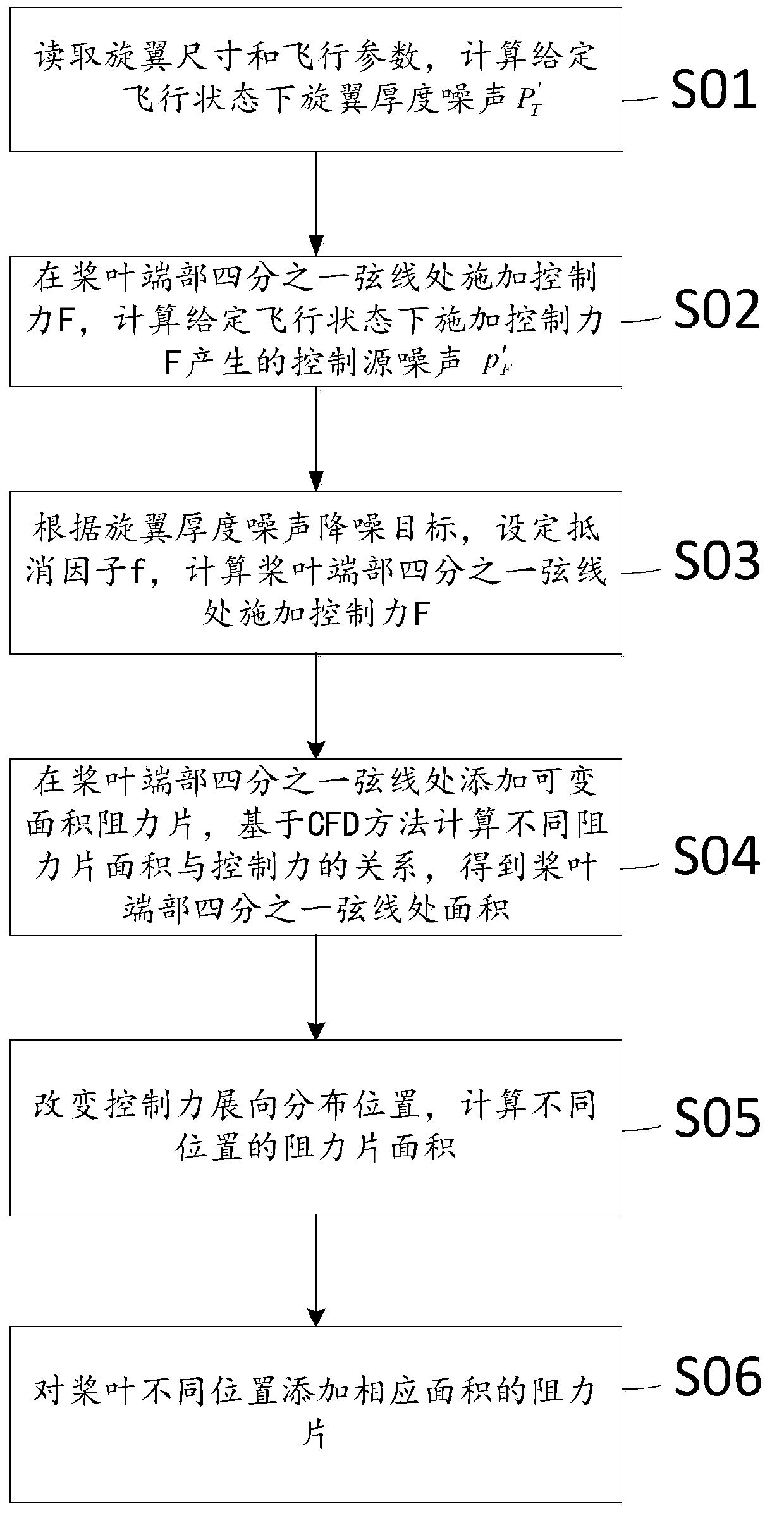
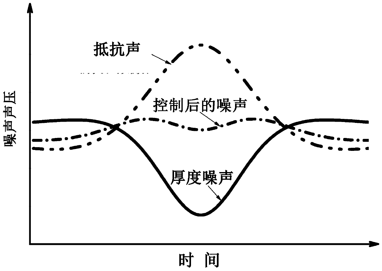
The embodiment of the invention discloses a rotor wing thickness noise control method based on variable area resistance sheets and relates to the technical field of aeroacoustics. Rotor wing thickness noise can be remarkably reduced in a targeted mode. The method comprises the steps that the rotor wing size and flight parameters are read, and rotor wing thickness noise P'T in a given flight state is calculated; a control force F is exerted at the quarter chord wire position of the end of each blade, and control source noise p'F produced by the control force F in the given flight state is calculated; according to a rotor wing thickness noise reducing target, an offset factor f is set, and the control force F exerted at the quarter chord wire position of the end of each blade is calculated; the variable area resistance sheet is added at the quarter chord wire position of the end of each blade, the area and control force relations of different resistance sheets are calculated based on a CFD method, and the area of the resistance sheet at the quarter chord wire position of the end of each blade is obtained; the spanwise distribution positions of the control forces are changed, and the areas of the resistance sheets at different positions are calculated; the resistance sheets with corresponding areas are added at the different positions of the blades.

Description

technical field [0001] The invention relates to the technical field of aeroacoustics, in particular to a rotor thickness noise control method based on a variable-area resistance sheet. Background technique [0002] With the widespread use of helicopters, the disadvantage of high noise has attracted more and more attention, making the noise of helicopters a problem that needs to be considered in the process of helicopter design. Rotor noise is the most important part of helicopter noise. Rotor noise can be divided into thickness noise, load noise, propeller-vortex interference noise, and high-speed pulse noise. Rotor thickness noise is produced by the blades periodically displacing the air. It has the characteristics of low frequency and propagating within the paddle disk, and the propagation distance is relatively long. It is the main object of acoustic detection. Exploration can effectively suppress or even eliminate the adverse effects of rotor thickness noise. The impact...

Claims


Application Information

Patent Timeline
Patent Type & Authority Patents(China)
IPC IPC(8): G06F30/15G06F119/10
CPCG06F30/15G06F2119/10Y02T90/00
Inventor 史勇杰贺祥杨玉成徐国华
Owner NANJING UNIV OF AERONAUTICS & ASTRONAUTICS
Why Eureka
Try Eureka