
Circulating currency box with temporary storage function and working method thereof

A cash box and functional technology, applied in the field of circular cash boxes, can solve the problems of increasing banknote deposit time and running problems, increasing equipment costs, and having no temporary storage function, etc., and achieves easy installation and maintenance, fast conversion speed, and structural simple effect

Inactive Publication Date: 2017-09-29
CASHWAY FINTECH CO LTD
View PDF6 Cites 5 Cited by
  • Summary
  • Abstract
  • Description
  • Claims
  • Application Information

AI Technical Summary

Problems solved by technology

[0005] The function of the recirculating cash box is to deposit and withdraw banknotes. There is no temporary storage function. The mechanism itself has a temporary storage mechanism. In this way, when depositing, the banknotes need to enter the temporary storage mechanism first, and then the banknotes enter the recirculation cash box from the temporary storage mechanism to complete the deposit action. First enter the temporary storage mechanism, which increases the deposit time of banknotes and the probability of problems in operation, and the existence of the temporary storage mechanism also increases the cost of equipment

Method used


Image

  • Circulating currency box with temporary storage function and working method thereof
  • Circulating currency box with temporary storage function and working method thereof
  • Circulating currency box with temporary storage function and working method thereof

Examples


Embodiment Construction

[0024] The specific embodiments of the present invention will be described in detail below with reference to the accompanying drawings and preferred embodiments.

[0025] In the description of the present invention, it should be understood that the terms "center", "portrait", "horizontal", "front", "rear", "left", "right", "vertical", "horizontal", The orientation or positional relationship indicated by "top", "bottom", "inner", "outer", etc. is based on the orientation or positional relationship shown in the drawings, and is only for the convenience of describing the present invention and simplifying the description, rather than indicating or implying that The device or element referred to must have a particular orientation, be constructed and operate in a particular orientation, and therefore should not be construed as limiting the invention.

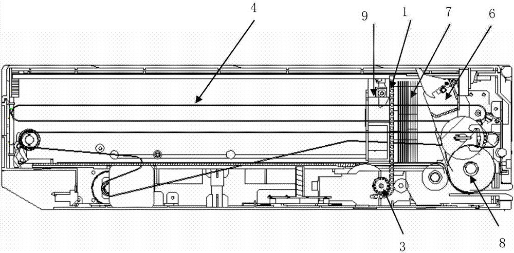
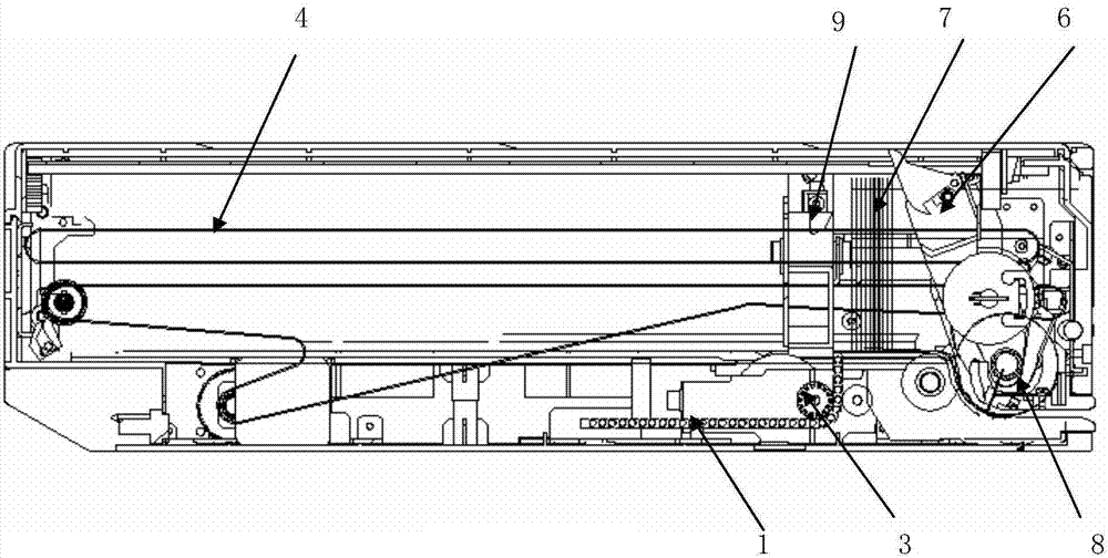
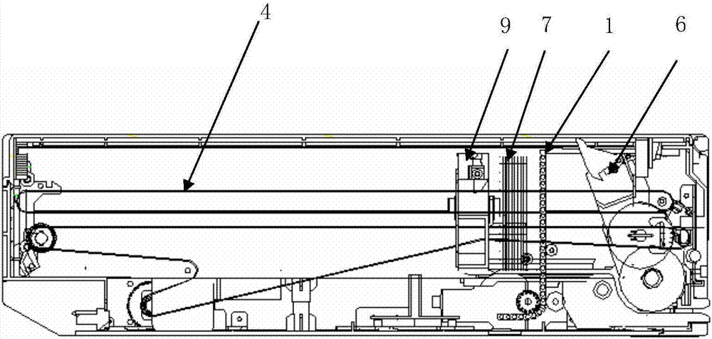
[0026] like Figure 1-Figure 4 As shown in the figure, a circulating cash box with a temporary storage function includes a temporar...


PUM


Abstract

The invention belongs to the technical field of automatic teller machines, and particularly relates to a circulating currency box with a temporary storage function. The circulating currency box with the temporary storage function comprises a temporary storage pushing plate arranged in the currency box; the temporary storage pushing plate has a track-type structure; two ends of the temporary storage pushing plate are in sliding match with a guiding groove arranged at the inner side of the currency box; the bottom part of the currency box is provided with a lifting motor and a gear driven by the lifting motor; the gear is engaged with the temporary storage pushing plate, and thus, vertical movement of the temporary storage pushing plate is realized. Independent movement control on the pushing plate, the temporary storage pushing plate mechanism and an upper currency grinding and separating mechanism is realized, program control is simplified, the structure is simple, and the mounting and the maintenance are facilitated.

Description

technical field [0001] The invention belongs to the technical field of automatic teller machines, and in particular relates to a circulating cash box with a temporary storage function and a working method thereof. Background technique [0002] At present, financial self-service equipment is widely used in the market. The working mode of such an automatic cash transaction device is that when depositing, the user puts the banknotes into the cash-in and out-flow port, the gate is closed, and the banknotes are counted into the temporary storage mechanism inside the institution first. After confirming the deposit, the banknotes are deposited into the circulating cash drawer by the temporary deposit mechanism. If the user cancels depositing the banknotes, the banknotes will be returned to the banknote deposit and withdrawal port by the temporary storage mechanism, the gate will be opened, and the user will take out the banknotes. [0003] In the circulating cash box of the device...

Claims


Application Information

Patent Timeline
Patent Type & Authority Applications(China)
IPC IPC(8): G07D11/00G07F19/00
CPCG07D11/0096G07D11/14G07F19/00
Inventor 江浩然
Owner CASHWAY FINTECH CO LTD
Learn More