
Commutation torque fluctuation suppression method of brushless DC motor driven by non-inductive boost topology

A brushed DC motor and fluctuation suppression technology, applied in torque ripple control, electronic commutator and other directions, can solve the problem of many power switches of the front-stage DC-DC converter, increase the volume and cost of the drive system, and prolong the commutation process time. and other problems, to achieve the effect of shortening the commutation process time, less power devices, and simple topology structure

Active Publication Date: 2019-08-27
TIANJIN UNIV
View PDF4 Cites 0 Cited by
  • Summary
  • Abstract
  • Description
  • Claims
  • Application Information

AI Technical Summary

Problems solved by technology

[0004] However, there are still some problems in the existing commutation torque fluctuation suppression methods: For the PWM method, when the motor is running at a higher speed below the rated speed, under the limited inverter DC side voltage limit, this type of method cannot It is to suppress the commutation torque fluctuation by prolonging the off-phase current drop time, which will prolong the undesired commutation process time
For the existing front-stage DC-DC converter method, the power switches of the added front-stage DC-DC converter are more, and additional inductance needs to be added, which increases the size and cost of the drive system

Method used


Image

  • Commutation torque fluctuation suppression method of brushless DC motor driven by non-inductive boost topology
  • Commutation torque fluctuation suppression method of brushless DC motor driven by non-inductive boost topology
  • Commutation torque fluctuation suppression method of brushless DC motor driven by non-inductive boost topology

Examples


Embodiment Construction

[0043] The method for suppressing the commutation torque fluctuation of the brushless DC motor driven by the non-inductive boost topology of the present invention will be described in detail below with reference to the embodiments and the accompanying drawings.

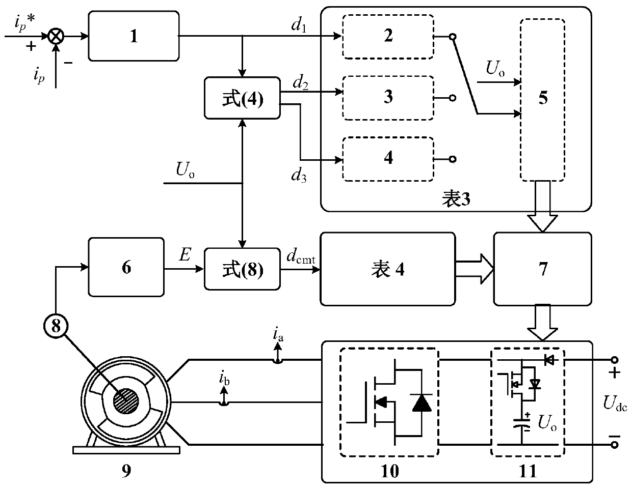
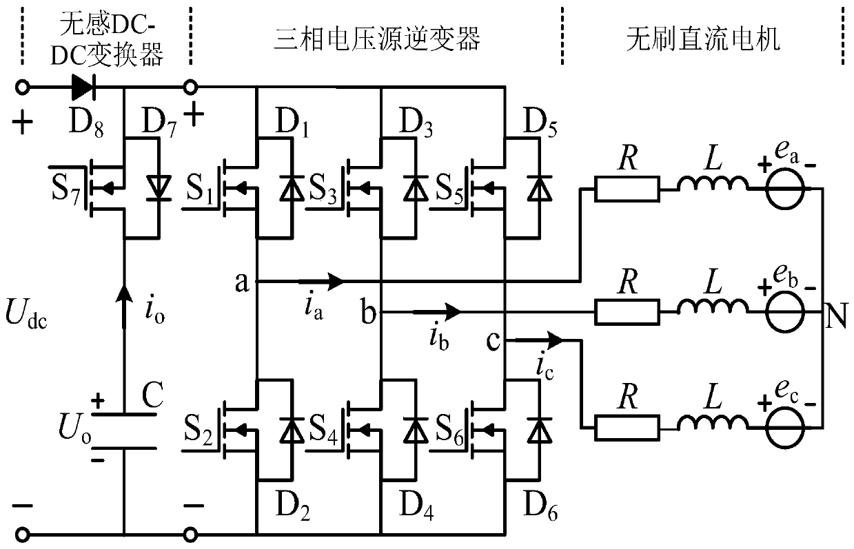
[0044] like figure 1 shown. The method for suppressing the commutation torque fluctuation of the brushless DC motor driven by the non-inductive boost topology of the present invention is a control method for selecting a non-commutation area or a commutation area by judging the working area. In the non-commutation area, the output voltage of the non-inductive DC-DC boost topology is adjusted under the premise of ensuring the normal speed regulation of the motor by selecting the working mode reasonably. In the commutation area, the output voltage of the non-inductive DC-DC boost topology is used, and a unified switching vector is used to suppress the commutation torque fluctuation and shorten the commutation time.

[...


PUM


Abstract

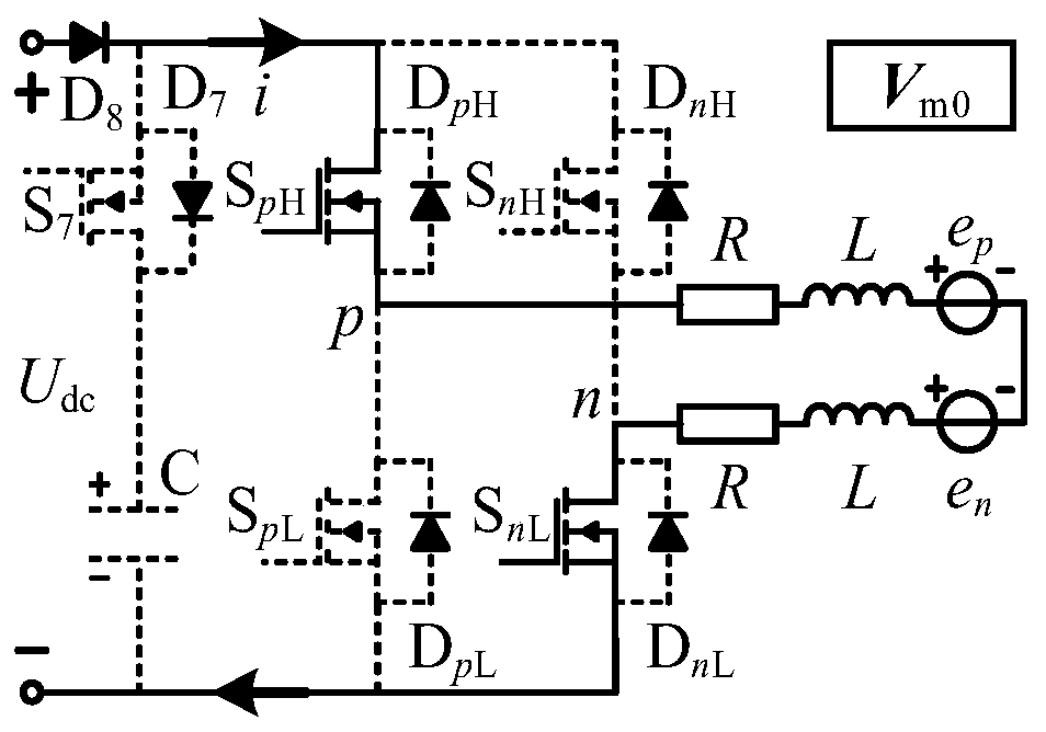
The invention provides a non-inductive boost topological driving brushless DC motor commutation torque ripple suppression method. A non-inductive DC-DC converter is designed to be additionally arranged before a three-phase voltage source inverter so that the overall system forms a non-inductive boost topological three-phase voltage source inverter driving circuit; the effect of different switching vectors on the motor input voltage and the non-inductive DC-DC converter output voltage is analyzed; when a brushless DC motor operates in the non-commutation stage, three working modes of a normal mode, a boost mode and a buck mode are designed according to the effect of the switching vectors; the output voltage of the DC-DC converter is regulated under the premise of guaranteeing normal speed regulation of the brushless DC motor by selecting three working modes; and when the brushless DC motor operates in the commutation stage, the two fixed switching vectors are adopted to suppress the commutation torque ripple of the brushless DC motor. The size and the cost of the driving system can be greatly saved, and the time of the commutation process can be effectively shortened in suppressing the commutation torque ripple so that the reliability of motor operation can be enhanced.

Description

technical field [0001] The invention relates to a brushless direct current motor. In particular, it relates to a method for suppressing commutation torque fluctuation of a brushless DC motor driven by a non-inductive boost topology. Background technique [0002] Brushless DC motors are widely used in industrial control, aerospace and electric vehicles due to their simple structure, high power density, and stable and reliable operation. However, since the motor inductance and the limited inverter voltage hinder the rapid change of the phase current during the commutation process, the motor generates large torque fluctuations during the commutation process, and the maximum commutation torque fluctuation can reach 100% of the average torque. 50%. The commutation torque fluctuation will cause vibration and noise of the motor system, and reduce the load capacity of the motor, which is one of the main problems that limit the high-performance operation of brushless DC motors. ...

Claims


Application Information

Patent Timeline
Patent Type & Authority Patents(China)
IPC IPC(8): H02P6/10H02P6/14
Inventor 夏长亮姜国凯李新旻陈炜史婷娜
Owner TIANJIN UNIV
Learn More