Auxiliary instrument for anorectal operation

A technology of surgery and instruments, which is applied in the field of auxiliary instruments for surgical operations, can solve the problems of inconvenient use and inability to realize single-person operation, and achieve the effect of convenient use and convenient operation

Inactive Publication Date: 2017-10-03
SHANGHAI YISI MEDICAL TECH CO LTD +1
View PDF4 Cites 2 Cited by
  • Summary
  • Abstract
  • Description
  • Claims
  • Application Information

AI Technical Summary

Problems solved by technology

However, during use, it was found that the existing suturing device does not have a fixed structure that cooperates with the anal expander seat. During the operation, the doctor needs an assistant to

Method used


Image

  • Auxiliary instrument for anorectal operation
  • Auxiliary instrument for anorectal operation
  • Auxiliary instrument for anorectal operation

Examples


Embodiment approach 1

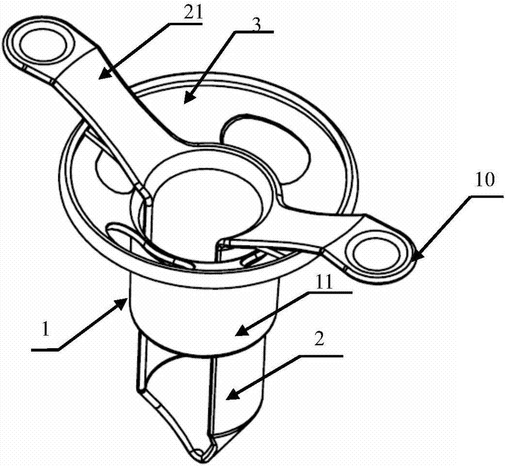
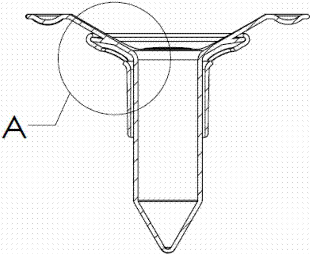
[0031] In one embodiment of the present application, as Figure 1-4 As shown, the present application provides an auxiliary instrument for anorectal surgery, including an anal dilator seat 1 and a suturing device 2 . See attached Figure 4 , the anal dilator seat 1 includes a hollow body 11 and a trumpet-shaped suture portion located at the proximal end of the body, and the body 11 and the suture portion can be integrally formed. Figure 1-4 The shown body 11 is a cylindrical structure, and the body 11 includes a distal end that goes deep into the patient's anus and a proximal end that is opposite to the distal end and is close to the operator. The distal end of the anal dilator seat 1 can directly pass through the Anus or through the anus to reach the surgical site with the assistance of other instruments, the distal end is straight or cone-shaped. Such as Figure 1-4 As shown, the sutured portion is a broadside 3 whose peripheral diameter is larger than that of the main b...

Embodiment approach 2

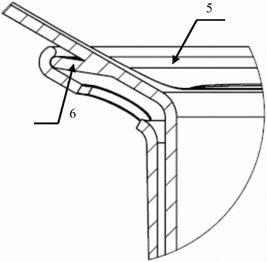
[0038] Refer below Figure 5-8 The second embodiment of the present application will be described, and most of the structures of this embodiment are the same as those of the above-mentioned first embodiment, and these same structures are denoted by the same reference numerals. The difference between this embodiment and the first embodiment is that the mutual fixing structure between the anal dilator seat 1 and the suturing device 2 is different, see the attached Figure 5-8 , the edge portion of the wide side 3 of the anal dilator seat 1 may not be provided with an annular groove 5 (the ring annular groove 5 may also be provided). The surface of the wing part 21 of the stapler 2 is provided with an outwardly protruding fitting structure 7, and the fitting structure 7 includes a hook 8 protruding outward from the distal surface of the wing part 21 and a hook 8 protruding from the wing part. The outwardly protruding plectrum 9 on the near side surface of 21. See attached Fig...


PUM


Abstract

The invention relates to the technical field of implantable medical devices and particularly discloses an auxiliary instrument for anorectal operation. The auxiliary instrument comprises an anal dilatation device base and a transfixion device. Fixing structures are arranged on the anal dilatation device base and the transfixion device, and the fixing structure of the anal dilatation device base and the fixing structure of the transfixion device are mutually matched to achieve relative fixing between the anal dilatation device base and the transfixion device. The auxiliary instrument is characterized in that the fixing structure of the anal dilatation device base and the fixing structure of the transfixion device can be relatively separated to adjust the relative positions between the anal dilatation device and the transfixion device. By arranging the mutually matched fixing structures between the transfixion device and an anal dilatation device, the transfixion device can be accurately and fixedly connected with any position of the edge of the anal dilatation device base during operation, and the auxiliary instrument is convenient to operate, easy to manufacture and lower in cost.

Description

technical field [0001] The present application relates to an auxiliary device for surgical operation, in particular to an auxiliary device for anorectal operation. Background technique [0002] In anorectal surgery, "suprahemorrhoidal mucosal excision" (PPH operation) is the most common treatment method, and the prolapsed mucosal band is excised with a PPH stapler. In the existing PPH operation, the anal expander seat and the suturing device are often used as auxiliary instruments in the operation, and the anal expander seat is a commonly used surgical instrument in anorectal surgery, and plays an important role in the anorectal examination and surgical treatment. . The currently commonly used anal dilator seat is a straight cylindrical structure with edges, and its edges are controlled by a doctor or directly fixed with the skin of the anus edge. The function of the anal expander seat is to open the anus and prepare for the follow-up examination or treatment. In the PPH ...

Claims


Application Information

Patent Timeline
IPC IPC(8): A61M29/00A61B17/04
CPCA61B17/0491A61B2017/00862A61M29/00A61M2210/1067
Inventor 王磊聂红林余惠玲
Owner SHANGHAI YISI MEDICAL TECH CO LTD
Why Eureka
Try Eureka