Grouting device in ceramic production process

A technology of production process and grouting device, which is applied to supply devices, ceramic molding machines, manufacturing tools, etc., can solve the problems of insufficient injection volume, difficulty in automatically controlling the amount of injected slurry, affecting the production quality of ceramic workpieces, etc., so as to avoid waste. , The effect of automatic and precise control of the injection volume

Active Publication Date: 2017-10-03
大埔县发源发展有限公司
View PDF5 Cites 2 Cited by
  • Summary
  • Abstract
  • Description
  • Claims
  • Application Information

AI Technical Summary

Problems solved by technology

[0002] The development history of ceramics is an important part of the history of Chinese civilization. As one of the four ancient civilizations, China has made outstanding contributions to the progress and development of human society. Among them, the invention of ceramics has unique significance. In the production process, the mold is firstly positioned, the mold is sent to the grouting station and ceramic slurry is injected into the forming mold, and the green body can be formed after the ceramic slurry is formed in the mold. The existing grouting equipment is generally very It is difficult to automatically control the amount of injected slurry, and it is easy to cause insufficient injection amount or excessive injection amount to overflow, which will affect the production quality of ceramic workpieces. In view of this, we propose a grouting device in the process of ceramic production

Method used


Image

  • Grouting device in ceramic production process
  • Grouting device in ceramic production process

Examples


Embodiment Construction

[0014] The following will clearly and completely describe the technical solutions in the embodiments of the present invention with reference to the accompanying drawings in the embodiments of the present invention. Obviously, the described embodiments are only some, not all, embodiments of the present invention. Based on the embodiments of the present invention, all other embodiments obtained by persons of ordinary skill in the art without making creative efforts belong to the protection scope of the present invention.

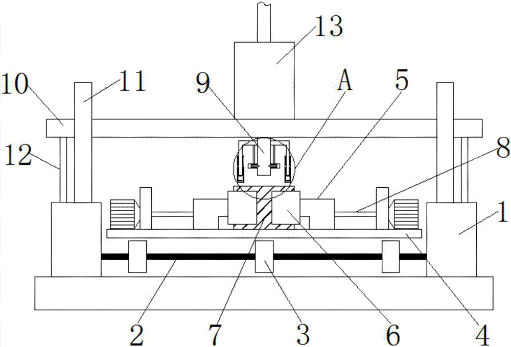
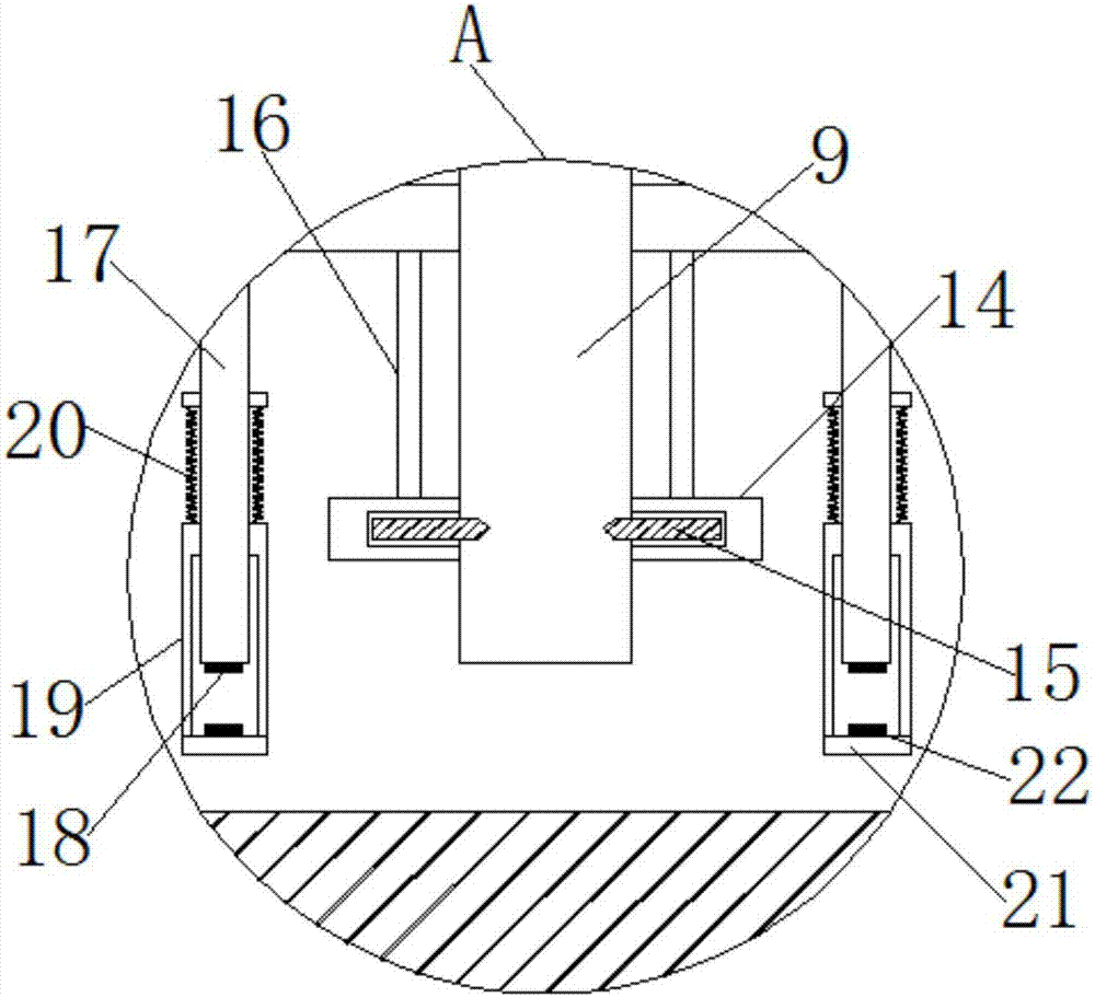
[0015] see Figure 1-2 , the present invention provides a technical solution:

[0016] A grouting device in the ceramic production process, including a workbench, two support bases 1 are installed on the workbench, a rotating shaft 2 is connected between the two support bases 1, and the rotating shaft 2 is connected to the motor shaft inside the support base 1, In addition, a plurality of transmission wheels 3 are installed on the rotating shaft 2, and a tran...


PUM


Abstract

The invention relates to the technical field of ceramic machinery, in particular to a grouting device in a ceramic production process. The grouting device comprises a workbench, wherein two support seats are installed on the workbench, and a rotating shaft is connected between the two support seats. According to the device, a grouting cylinder is installed on a support plate on the support seats, a mold is installed below a grout outlet tube on the grouting cylinder, and automatic grouting for the mold can be achieved. Seals and support frames are installed on two sides of the grout outlet tube, second contact piece support rods are movably installed on the corresponding support frames, floating blocks on the corresponding second contact piece support rods are pushed by grout in the mold to move vertically, and accordingly, contact and separation of the two contact pieces can be realized, the effect of connecting electrification coils in the seals is achieved, and sealing and unsealing of the grouting tube by sealing plates is achieved by acting force of an induction metal block on the sealing plates. In this way, the effect of automatic and accurate control of the injection amount of the grout is achieved, and waste or insufficient injection is avoided.

Description

technical field [0001] The invention relates to the technical field of ceramic machinery, in particular to a grouting device in the ceramic production process. Background technique [0002] The development history of ceramics is an important part of the history of Chinese civilization. As one of the four ancient civilizations, China has made outstanding contributions to the progress and development of human society. Among them, the invention of ceramics has unique significance. In the production process, the mold is firstly positioned, the mold is sent to the grouting station and ceramic slurry is injected into the forming mold, and the green body can be formed after the ceramic slurry is formed in the mold. The existing grouting equipment is generally very It is difficult to automatically control the amount of injected slurry, and it is easy to cause insufficient injection amount or excessive injection amount to overflow, which affects the production quality of ceramic work...

Claims


Application Information

Patent Timeline
IPC IPC(8): B28B13/02B28B1/26
CPCB28B1/26B28B13/0275
Inventor 不公告发明人
Owner 大埔县发源发展有限公司
Why Eureka
Try Eureka