Making machine used for production of air column bags for packaging

An air column bag and bag making machine technology, which is applied in packaging, bag making operations, transportation and packaging, etc., can solve the problems of high production cost and low efficiency, and achieve time and energy saving, convenient operation and high feeding efficiency high effect

Inactive Publication Date: 2017-10-03
佛山市捷信来包装材料有限公司
7 Cites 5 Cited by

AI-Extracted Technical Summary

Problems solved by technology

[0003] However, the existing bag-making machines generally stick the one-way valv...

Method used

A plurality of pneumatic rollers and rotating rollers of the feeding device 100 of the bag making machine for producing packaging air column bags provided by the present invention can be used alone, and can also be used in conjunction with feeding, depending on actual conditions, convenient Material conveying, high feeding efficiency, convenient operation, can save a lot of time and energy of the staff. During the production process of the air column bag, the heat sealing device 200 moves the air column bag between the hot pressing plate 212 and the backing plate 206, so that the hot pressing plate 212 can be moved to a suitable position for heat sealing. disc 205, so as to facilitate the rotation of the screw rod 204, so that the end of the screw rod 204 away from the adjustment disc 205 is against the support plate 207, so that the position of the connecting rod 203 is conveniently fixed, and then the L-shaped sliding seat is fixed to prevent the L-shaped sliding seat from moving. To prevent the shaking of the hot platen when the air column bag is heat sealed, due to the driving effect of the hydraulic push rod 209, it is convenient to move the pressing block to the stabilizing bar 213, and the stabilizing bar 213 is inserted into the pressing groove, thereby facilitating the resisting The pressing block is in contact with the mounting plate, so that the hot pressing plate can heat seal the air column bag. Due to the elastic force of the first spring 214 and the second spring 215, it is convenient for the hot pressing plate to stay away from the air column bag after the heat sealing is completed. Realize the heat sealing of the one-way valve between the air column bags, and then use the pulling device 300 to remove the dust and flatten the air column bags that need to be pulled through the dust removal pressing roller on the fixed frame, and then place the air column bags in the On the flat material pressing plate 317, then start the pulling drive cylinder 306 to drive the active pulling wheel 319 to rotate. Since the passive pressing wheel 316 presses the air column bag and fits the active pressing wheel 319, the air column bag follows the active pressing. The material wheel pulls the material, and the other end of the material pulling table is provided with a bracket 312 and a pressure plate 310, which can further press the flattened air column bag, and the glass plate arranged on the side of the material pulling table can pass through The hinges and handles can be opened conveniently, quickly realize the production of air column bags, and effectively improve the production efficiency of air column bags.
As shown in Figure 2, this feeding device 100 comprises feeding base 101, and feeding base 101 adopts 304 stainless steel to make, is convenient to clean, and is durable in use, and service life is long, and feeding base 101 is provided with cabinet 106, and cabinet 106 is equipped with There is a driving motor, and one side of the cabinet 106 is provided with a first connecting seat 105 and a second connecting seat 108, a row of first rotating rollers 104 are rotatably connected on the first connecting seat 105, and two rollers 104 are rotatably connected on the second connecting seat 108. Rotating rod 109, two rotating rods 109 are provided with fixed frame 110 away from the side of second connecting seat 108, are provided with second rotating roller between second connecting seat 108 and fixed frame 110, and one side of cabinet 106 is also arranged in parallel There is a row of the third turning roller 107 and a turning post, the turning post is sheathed with coil material 103, the first turning roller 104, the second turning roller, the third turning roller 107 and the turning post all go through the cabinet 106 and are connected with the drive motor The driving end is connected, and a frame body 116 is provided on one side of the feeding base 101. The feeding base 101 and the frame body 116 adopt an integrally formed structure, and three first pneumatic rollers 115 are rotatably connected to the frame body 116. Two fixed blocks, the second pneumatic roller 114 is arranged between the two fixed blocks, and the air motor 117 is arranged on the frame body 116, and the air motor 117 is welded on the frame body 116 to ensure the stability of the air motor 117. Also be provided with fixed seat 111, the upper end of fixed seat 111 is provided with rotating seat 113, is also provided with connecting rod 112 on rotating seat 113, and the lower end of feeding base 101 is provided with a plurality of connecting frames, and each connecting frame is provided with rolling The wheel 102 and the rolling wheel 102 are provided with anti-slip lines, and the setting of the rolling wheel 102 makes the device moveable.
As shown in Figure 3a and Figure 3b, this heat-sealing device comprises two support plates 201 that are arranged in parallel, the upper end of two support plates 201 is connected by backing plate 206, the upper end of two support plates 201 opposite sides Two L-shaped sliding seats 202 are symmetrically arranged, and the L-shaped sliding seats 202 are slidably connected with the supporting plate 201. Sliders are arranged on the inner walls of both sides of the L-shaped sliding seat 202, and the supporting plate 201 is provided with corresponding sliders. The chute, due to the contact between the slider and the inner wall of the chute, prevents the L-shaped slide 202 from the support plate 201, and the two L-shaped slides 202 on the same side are connected by a connecting rod 203, and the connecting rod 203 is far away from the support plate 201. One side of the support plate 201 is threadedly connected with a screw rod 204, one end of the screw rod 204 runs through the connecting rod 203 and is offset against the support plate 201, and the other end of the screw rod 204 is fixedly connected with an adjustment disc 205, and the surface of the adjustment disc 205 is provided with anti-slip lines, which increases Large friction coefficient increases frictional force, thereby preventing slipping. The upper side of the L-shaped sliding seat 202 is fixedly connected with a vertically arranged support rod 207, and the opposite ends of the two supporting rods 207 away from the L-shaped sliding seat 202 are fixed The rod 208 is connected, the two ends of the lower side of the fixed rod 208 are fixedly connected with th...

Abstract

The invention relates to a bag making machine for producing air column bags for packaging, comprising a conveyor belt, and a feeding device (100), a heat sealing device (200) and a material pulling device (300) arranged in sequence along the moving direction of the conveyor belt ), the feeding device includes a feeding base (101), the feeding base (101) is provided with a cabinet (106); the heat sealing device includes two supporting plates (201) arranged in parallel, and the two supporting The upper end of the plate (201) is connected by a backing plate (206), and the pulling device includes a pulling table (304), and the lower end of the pulling table (304) is provided with two supports (312) in the car. . The multiple pneumatic rollers and rotating rollers of the feeding device of the bag making machine used for producing air column bags for packaging provided by the present invention can be used independently, which is convenient for material transportation, has high feeding efficiency, is convenient to operate, and can save a lot of time for workers and energy, effectively improving the production efficiency of the air column bag.

Application Domain

Technology Topic

Image

  • Making machine used for production of air column bags for packaging
  • Making machine used for production of air column bags for packaging
  • Making machine used for production of air column bags for packaging

Examples

  • Experimental program(1)

Example Embodiment

[0040] The present invention will be further described below in conjunction with the drawings.
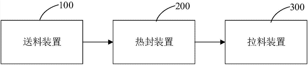
[0041] Such as figure 1 As shown, a bag making machine for producing air column bags for packaging includes a conveyor belt, and a feeding device 100, a heat sealing device 200, and a material pulling device 300 arranged in sequence along the moving direction of the conveyor belt.
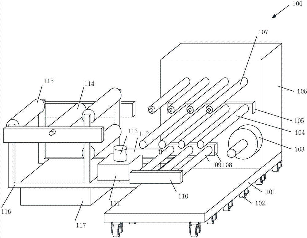
[0042] Such as figure 2 As shown, the feeding device 100 includes a feeding base 101. The feeding base 101 is made of 304 stainless steel, which is easy to clean, durable, and has a long service life. The feeding base 101 is provided with a chassis 106, and the chassis 106 is provided with a driving motor. A first connecting seat 105 and a second connecting seat 108 are provided on one side of the first connecting seat 105. A row of first rotating rollers 104 are rotatably connected to the first connecting seat 105. Two rotating rods 109 are rotatably connected to the second connecting seat 108. The side of the rotating rod 109 away from the second connecting seat 108 is provided with a fixing frame 110, a second rotating roller is arranged between the second connecting seat 108 and the fixing frame 110, and a row of third rotating rollers is also arranged in parallel on one side of the chassis 106 107 and a rotating column, the rotating column is sleeved with a coil 103, the first rotating roller 104, the second rotating roller, the third rotating roller 107 and the rotating column all penetrate the chassis 106 and are connected with the driving end of the driving motor, and the feeding base One side of 101 is provided with a frame body 116. The feeding base 101 and the frame body 116 adopt an integral structure. Three first pneumatic rollers 115 are rotatably connected to the frame body 116. The frame body 116 is also provided with two fixed blocks symmetrically. A second pneumatic roller 114 is arranged between the two fixed blocks. The frame 116 is provided with a pneumatic motor 117. The pneumatic motor 117 is welded to the frame 116 to ensure the stability of the pneumatic motor 117. The pneumatic motor 117 is also provided with a fixed seat 111 , The upper end of the fixed seat 111 is provided with a rotating seat 113, the rotating seat 113 is also provided with a connecting rod 112, the lower end of the feeding base 101 is provided with a plurality of connecting frames, and each connecting frame is provided with a rolling wheel 102, a rolling wheel 102 There are anti-skid patterns, and the setting of the rolling wheel 102 makes the device movable.
[0043] In the present invention, when the device is used, the plastic film is twisted through the first pneumatic roller 115, the second pneumatic roller 114, the first rotating roller 104 and the third rotating roller 107, etc. and finally wound on the rotating rod. The second pneumatic roller 114 and the first pneumatic roller 115 are rotated by pneumatics. The first rotating roller 104, the second rotating roller, the third rotating roller 107 and the rotating column are driven to rotate by the driving motor in the case 106. The multiple pneumatic rollers in this device It can be used alone or in conjunction with the rotating roller for feeding, depending on the actual situation; the rotating seat 113 can be rotated to drive the connecting rod 112, and then adjust the position of the connecting rod 112, which can be adjusted according to the actual situation to facilitate the material The setting of the rolling wheel 102 facilitates the movement of the entire device, and the rolling wheel 102 is provided with anti-skid patterns to ensure the stability of the overall structure when moving.
[0044] Such as Figure 3a with Figure 3b As shown, the heat sealing device includes two support plates 201 arranged in parallel. The upper ends of the two support plates 201 are connected by a backing plate 206. The upper ends of the two support plates 201 opposite to each other are symmetrically provided with two L-shaped sliding plates. The L-shaped sliding seat 202 is slidably connected to the support plate 201. Sliders are provided on both inner walls of the L-shaped sliding seat 202. The support plate 201 is provided with sliding grooves corresponding to the sliding blocks. The contact of the inner side wall of the groove prevents the L-shaped sliding seat 202 from being separated from the support plate 201. The two L-shaped sliding seats 202 on the same side are connected by a connecting rod 203. The connecting rod 203 is screwed on the side away from the support plate 201. Screw 204, one end of the screw 204 penetrates the connecting rod 203 and abuts against the support plate 201, and the other end of the screw 204 is fixedly connected with an adjustment disc 205. The surface of the adjustment disc 205 is provided with anti-skid patterns to increase the coefficient of friction and increase the friction. In order to prevent slipping, the upper side of the L-shaped sliding seat 202 is fixedly connected with a vertically arranged support rod 207, and the two oppositely positioned support rods 207 are connected at one end away from the L-shaped sliding seat 202 by a fixed rod 208, and the lower side of the fixed rod 208 Both ends of the hydraulic push rod 209 are fixedly connected with a hydraulic push rod 209, and the output end of the hydraulic push rod 209 is fixedly connected with a pressure block 210. The four pressure blocks 210 are provided with a mounting plate 211 on the side away from the hydraulic push rod 209. A hot pressing plate 212 corresponding to the position of the backing plate 206 is provided on the lower side. The hot pressing plate 212 is fixedly connected to the mounting plate 211 by a plurality of locking screws. The side of the hot pressing plate 212 away from the mounting plate 211 is provided with a plurality of protrusions. Block 217, the convex block 217 is provided with a heating wire. Due to the heating of the heating wire, the convex block is in contact with the air column bag, which facilitates the fixing and bonding of the two sides of the air column bag. The air column bag is divided into multiple columnar partitions for installation. The four corners of the plate 211 are respectively provided with sockets corresponding to the positions of the four pressure blocks 210. The sockets are provided with a stabilizer bar 213. The inner side wall of the socket and the surface of the stabilizer bar 213 are coated with grease to reduce the friction coefficient. , To reduce friction, so as to facilitate the movement of the stabilizer bar 213 in the socket, one end of the stabilizer bar 213 is fixedly connected to the upper side of the L-shaped sliding seat 202, and the pressure block 210 is provided with a pressure groove corresponding to the stabilizer bar 213, The upper end of the stabilizer bar 213 is sleeved with a first spring 214. The two ends of the first spring 214 are respectively connected with the stabilizer bar 213 and the pressing block 210. The lower end of the stabilizer bar 213 is sleeved with a second spring 215. One end is connected to the L-shaped sliding seat 202, and the other end of the second spring 215 is connected with a pressure ring 216. The pressure ring 216 is slidably sleeved on the stabilizer bar 213. The pressure ring 216 is mounted on the side away from the second spring 215. The plate 211 is offset.
[0045] In the present invention, during the production process of the air column bag, the air column bag moves between the hot pressing plate 212 and the backing plate 206. By moving the L-shaped sliding seat 202, it is convenient for the support rod 207 to drive the mounting plate 211 and the hot pressing plate 206. The plate 212 moves to facilitate the movement of the hot pressing plate 212 to a suitable position for heat sealing. By rotating the adjusting plate 205, the screw 204 is facilitated to rotate, so that the end of the screw 204 away from the adjusting plate 205 abuts against the support plate 201, thereby facilitating Fix the position of the connecting rod 203, and then fix the L-shaped sliding seat 202 to prevent the L-shaped sliding seat 202 from moving, so as to prevent the shaking of the hot plate 212 when the air column bag is heat-sealed, due to the hydraulic push rod 209 Drive action to facilitate the movement of the pressure block 210 to the stabilizer bar 213, and the stabilizer bar 213 is inserted into the pressure groove, thereby facilitating the pressure block 210 to contact the mounting plate 211, thereby facilitating the heat-sealing of the air column bag by the hot plate 212 Because of the elastic force of the first spring 214 and the second spring 215, it is convenient to keep the hot pressing plate 212 away from the air column bag after the heat sealing is completed, and the stabilizer bar 213 can prevent the mounting plate 211 from shaking during the up and down movement, thereby Affect the heat sealing effect.
[0046] Such as Figure 4a with Figure 4b As shown, the pulling device includes a pulling table 304. The side walls of the two ends of the pulling table 304 are equipped with adjusting knobs 305. The lower end of the pulling table 304 is provided with two support seats 312 in the car. The pulling table 304 A fixed frame 301 is provided on one side of the fixed frame 301, a dust removal pressing roller 302 is arranged on the fixed frame 301, a bracket 309 is arranged on the other side of the pulling table 304, and a plurality of pressing plates 310 are arranged on the bracket 309, the upper end of the bracket 309, etc. There are several grooves in the distance, each groove is provided with a vertical upward spring, and the spring and the pressing plate 310 are fixedly connected, and a conveyor belt 303 is inserted between the fixing frame 301, the pulling table 304 and the bracket 309 , The upper end of the pull table 304 is also provided with two symmetric pull drive cylinders 306, each pull drive cylinder 306 is connected with two connecting pipes 308, and the two connecting pipes 308 are fixed by a fixing clip 311 On the support 312, the upper surface of the pull table 304 is provided with a mounting plate 313, the mounting plate 313 is fixed to the upper end of the pull table 304 by a locking screw, and the side of the mounting plate 313 away from the fixing frame 301 is hinged by a hinge 314 There is a glass plate 315, the lower side of the pull table 304 is provided with an active pull wheel 319, and the active pull wheel 319 is connected to the pull drive cylinder 306 through a connecting tube 308, and the upper side of the active pull wheel 319 is provided with a rotating rod 318. A plurality of passive pulling wheels 316 are equidistantly arranged on the rotating rod 318, and a flat material pressing plate 317 is arranged between the passive pulling wheel 316 and the active pulling wheel 319, which can increase the efficiency of pulling materials.
[0047] In the present invention, when the device is used, the air column bag to be pulled is passed through the dust removal pressing roller 302 on the fixed frame 301 for dust removal and flattening, and then the air column bag is placed on the flat material pressing plate 317, and then Restart the pulling drive cylinder 306 to drive the active pulling wheel 319 to rotate. The angle of the active pulling wheel 319 can be fine-tuned through the adjustment knob 305. Because the passive pressing wheel 316 presses the air column bag and fits the active pressure The material wheel 319, the air column bag is pulled along with the active pressing wheel 319, and the other end of the drawing table is provided with a bracket 309 and a pressing plate 310, which can further press the air column bag after being flattened, and set The glass plate 315 on the side of the pulling table 304 can be easily opened by the hinge 314 and the handle 307 to facilitate maintenance and cleaning of the components therein.
[0048] Such as Figure 5 As shown, the cooling device includes a cooling base 401. The lower end of the cooling base 401 is provided with a support leg 402. Both sides of the upper end of the cooling base 401 are provided with support rods 414. The support rods 414 are provided with electric slide rails. The switch of the slide rail causes the mounting plate 413 to drop. A fixed plate 411 is provided between the two electric slide rails. The lower end of the fixed plate 411 is provided with two cylinders 410. The cylinder 410 is provided with guide pins 412 and 412 The position of the mounting plate 413 will not be shifted during the pressing process. The guide pin 412 is fixedly connected to the side wall of the cylinder 410. The lower end of the guide pin 412 is provided with a mounting plate 413, and the upper end of the mounting plate 413 is provided with The circular cavity corresponding to the position of the guide pin 412, the side wall of the circular cavity is provided with a plurality of sliding grooves, and a limit rod 415 is arranged in the sliding groove. The limit rod 415 is fixedly connected to the side wall of the sliding groove through an elastic device 416. The upper end of the 415 is provided with a pull rod 407, and the upper end of the mounting plate 413 is provided with a strip groove. The strip groove penetrates the side wall of the mounting plate 413 and communicates with the sliding groove. The pull rod 407 penetrates the strip groove, and the guide pin 412 is away from the bottom of the cylinder 410 One end of the side wall is provided with a slot, the lower end of the guide pin 412 is located in the cavity, the limit rod 415 is locked in the slot, and the upper end of the cooling base 401 is provided with multiple sets of fixing mechanisms along the horizontal direction. Each set of fixing mechanisms includes Two fixed blocks 405. A rotating shaft 403 is provided between the two fixed blocks 405 in each group. A roller 406 is provided in the middle of the rotating shaft 403. The side wall of the roller 406 is provided with a plurality of placement cavities along the circumferential direction. There is a heat absorption layer 404, the middle of the mounting plate 413 is provided with a cooling copper tube 408, the cooling copper tube 408 is annularly arranged in the middle of the mounting plate 413, and the upper corner of the mounting plate 413 is provided with a cooling device 409. The lower end of the cooling device 409 and The refrigeration copper pipe 408 is fixedly connected.
[0049] In the present invention, a spring is sleeved in the middle of the guide pin 412, the cooling base 401 is integrally formed with the support leg 402, the material of the cooling base 401 is 304 stainless steel, the lower end of the support leg 402 is provided with anti-skid patterns, and the pull rod 407 is away from the limit rod 415 There is a handle on one end. In the present invention, the operator first turns on the switch of the refrigeration equipment 409, and when the temperature of the mounting plate 413 reaches a proper temperature, the delivered air column bag passes between the mounting plate 413 and the roller 406, and then turns on the electric slide rail When the mounting plate 413 is lowered to an appropriate position, the electric slide rail switch is turned off to cool the air column bag.
[0050] Such as Figure 6a , Figure 6b with Figure 6c As shown, the half-folding device includes a half-folding base 501. The upper side wall of the half-folding base 501 is vertically provided with two first brackets 502 arranged parallel to each other, and the two first brackets 502 pass through two first rotating shafts 503 respectively. A first driven roller 504 and a second driven roller 505 are rotatably connected. The first driven roller 504 is located directly above the second driven roller 505. The upper side wall of the foldable base 501 is also vertically provided with two parallel A second support 507 is provided, and a transmission roller 508 is rotatably connected between the two second supports 507 through a second rotating shaft 509, and the first driven roller 504, the second driven roller 505 and the transmission roller 508 are connected In the air column bag 506, the upper side wall of the half-folding base 501 is also provided with two strip-shaped grooves 510 with openings upwards, and the strip-shaped grooves 510 are located on both sides of the two first supports 502, and the strip-shaped grooves 510 are A threaded rod 511 is rotatably connected, and the threaded rod 511 is sleeved with a nut 512 matching it. The half-folding base 501 is a hollow structure, and the half-folding base 501 is provided with a driving motor, and the output shaft of the driving motor is provided with a first belt pulley, And the two threaded rods 511 are respectively sleeved with a second belt pulley corresponding to the first belt pulley. The driving motor can drive the two threaded rods 511 to rotate, so that the pressing roller 514 can be moved. The driving motor is a servo driving motor, which is convenient for control. The pressure roller 514 cyclically moves back and forth, the upper side wall of the nut 512 is fixedly connected with a vertically arranged telescopic bracket 513, the side walls on both sides of the strip groove 510 are provided with sliding grooves 515, and the nut 512 passes through the sliding block and the sliding groove 515 is slidably connected. A pressure roller 514 is rotatably connected between the two telescopic brackets 513 through a rotating member. The height of the pressure roller 514 is arranged flush with the driving roller 508. The second rotating shaft 509 is provided with a first opening facing the driving roller 508. Installation groove 516, and the bottom of the first installation groove 516 is connected with an installation block 518 through a first spring 517, both ends of the transmission roller 508 are provided with a second installation groove 519 matching the installation block 518, the second installation groove 519 The side walls are symmetrically provided with two elastic arc-shaped clips 525, and the side walls of the two elastic arc-shaped clips 525 are provided with rubber cushions. The surface of the rubber cushions is provided with multiple stripes, which can increase The firmness of the mounting block 518 in the second mounting groove 519, the side walls on both sides of the mounting block 518 are provided with grooves 520, and the bottom of the groove 520 is connected with a clamping block 521 through a second spring 522, and the first mounting groove The inner wall of the 516 is provided with a slot 523 that matches the locking block 521, the inner wall of the slot 523 is provided with anti-skid patterns, the side wall of the second shaft 509 is threadedly connected with a threaded push rod 524, and the threaded push rod 524 extends to the slot 523 In this case, the outer side wall of the threaded push rod 524 located outside the second rotating shaft 509 is wrapped with a protective pad to prevent the fingers from being damaged when the threaded push rod 524 is rotated.
[0051] The present invention has simple structure and convenient operation. During the production process of the packaging air column bag, the transmission operation is completed by the transmission between the first driven roller 504, the second driven roller 505 and the driving roller 508; when the double folding operation is required, The movement of the telescopic bracket 513 can be driven by rotating the two threaded rods 511 and the nut 512, thereby driving the pressure roller 514 to move. The pressure roller 514 will remove the air between the first driven roller 504 and the driving roller 508 during the movement. The column bag 506 is flattened to complete the folding operation of the air column bag 506. This operation can be automated, which saves time and effort, and improves the production efficiency of the air column bag 506; at the same time, the size of the gap after the air column bag 506 is folded in half depends on The diameter of the drive roller 508; therefore, if you need to change the size of the fold gap, you can replace the drive roller 508 with a different diameter. The user can turn the threaded push rod 524 so that the threaded push rod 524 is locked in the groove 523. The clamping block 521 of the yoke is pushed out, so that the installation block 518 is separated from the second installation groove 519 under the action of the first spring 517 and shrinks into the first installation groove 516, so as to facilitate the replacement of the transmission roller 508. After the replacement, The pressing roller 514 and the driving roller 508 can be adjusted to be flush with each other through the telescopic bracket 513, so as to facilitate the folding operation of the gaps of different sizes.
[0052] The multiple pneumatic rollers and rotating rollers of the feeding device 100 of the bag making machine for producing air-pillar bags for packaging provided by the present invention can be used alone or in combination for feeding, depending on the actual situation, which is convenient for conveying materials , The feeding efficiency is high, the operation is convenient, and the staff can save a lot of time and energy. In the production process of the air column bag, the heat sealing device 200 moves the air column bag between the hot pressing plate 212 and the backing plate 206, so that the hot pressing plate 212 can be moved to a suitable position for heat sealing. The plate 205 facilitates the rotation of the screw 204 so that the end of the screw 204 away from the adjustment plate 205 abuts against the support plate 207, thereby facilitating the fixing of the position of the connecting rod 203, and then fixing the L-shaped sliding seat to prevent the L-shaped sliding seat from moving. To prevent the swaying of the hot pressing plate when the air column bag is heat-sealed, due to the driving action of the hydraulic push rod 209, it is convenient for the pressure block to move to the stabilizer bar 213, and the stabilizer bar 213 is inserted into the pressure groove to facilitate the resistance. The pressure block is in contact with the mounting plate, so that the hot plate can heat-seal the air column bag. Due to the elastic force of the first spring 214 and the second spring 215, it is convenient to keep the hot plate away from the air column bag after the heat sealing is completed. The one-way valve is heat-sealed between the air column bags, and then the air column bag that needs to be pulled is removed and flattened by the material pulling device 300 through the dust removal pressing roller on the fixed frame, and then the air column bag is placed to Flat material pressing plate 317, and then start the material pulling drive cylinder 306 to drive the active material pulling wheel 319 to rotate. Because the passive material pressing wheel 316 presses the air column bag and fits the active material pressing wheel 319, the air column bag follows the active pressure The material wheel pulls the material, and the other end of the material drawing table is provided with a bracket 312 and a pressing plate 310, which can further press the flattened air column bag, and the glass plate arranged on the side of the material drawing table can pass through The hinges and handles can be opened conveniently and the production of the air column bag can be realized quickly, which effectively improves the production efficiency of the air column bag.
[0053] It should be understood that the present invention is not limited to the above-mentioned embodiments. Any changes or modifications to the present invention do not depart from the spirit and scope of the present invention. If these changes and modifications fall within the scope of the claims of the present invention and equivalent technical scope, then The present invention also means to include these modifications and variations.

PUM

no PUM

Description & Claims & Application Information

We can also present the details of the Description, Claims and Application information to help users get a comprehensive understanding of the technical details of the patent, such as background art, summary of invention, brief description of drawings, description of embodiments, and other original content. On the other hand, users can also determine the specific scope of protection of the technology through the list of claims; as well as understand the changes in the life cycle of the technology with the presentation of the patent timeline. Login to view more.

Similar technology patents

Adjustable-angle belt conveyor

InactiveCN102328804AAchieve angle adjustmentEasy to transportConveyorsRollersEngineeringOblique angle
Owner:WUXI JIESI LOGISTICS EQUIP

Plate-insert type patient transfer trolley

ActiveCN106236413AEasy to insertEasy to transportStretcherEngineeringPatient transfer
Owner:上海稼多医疗器械有限公司

Blood glucose sensor

ActiveUS20110015546A1Facilitate acquisitionEasy to transportCatheterSensorsMeasurement siteBiomedical engineering
Owner:EMBECTA CORP

Modular waste water treatment system

ActiveUS7097762B1Easy to transportEasily and inexpensively expandedBiological treatment regulationUsing liquid separation agentTruckWater treatment system
Owner:ICM +1

Classification and recommendation of technical efficacy words

  • Improve feeding efficiency
  • Easy to transport

Feeding device for medical accessories

InactiveCN105173627ASpace-saving layoutImprove feeding efficiencyConveyor partsMedical instruments
Owner:MAIDER MEDICAL IND EQUIP

Three-rail vibrating plate

Owner:ACME ELECTRONICS KUNSHAN
Why Eureka
Try Eureka