Check patentability & draft patents in minutes with Patsnap Eureka AI!

Current controller

A technology of current control and current control circuit, which is applied in the direction of electromagnetic circuit devices, lifting devices, electromagnets, etc., and can solve the problems of increasing current command, detection, and current deviation

Active Publication Date: 2017-10-03
TOYOTA IND CORP
View PDF6 Cites 3 Cited by
  • Summary
  • Abstract
  • Description
  • Claims
  • Application Information

AI Technical Summary

Problems solved by technology

The actual current is detected by the current detection circuit, but if a disconnection or momentary interruption occurs in the current detection circuit and the current flowing through the solenoid cannot be detected, the current deviation will increase, and the current command will also increase accordingly.

Method used


Image

  • Current controller
  • Current controller
  • Current controller

Examples


Embodiment Construction

[0010] Hereinafter, an embodiment in which the current control device is embodied as a vehicle control device will be described.

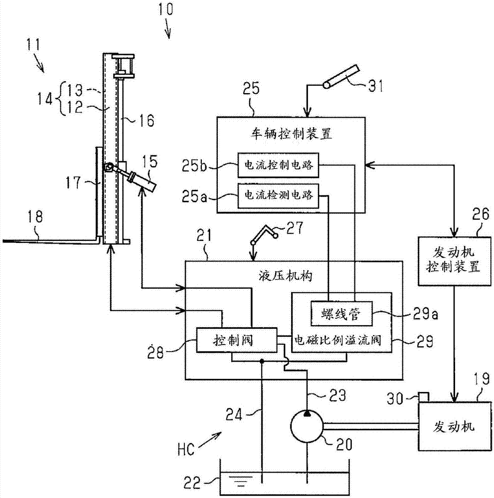
[0011] Such as figure 1 As shown, a forklift 10 as an industrial vehicle includes a loading and unloading device 11 . The loading and unloading device 11 includes a multistage mast 14 composed of a pair of left and right outer masts 12 and inner masts 13 . A hydraulic tilt cylinder 15 is connected to the outer mast 12 as a hydraulic working device, and a hydraulic lift cylinder 16 is connected to the inner mast 13 as a hydraulic working device. The mast 14 is tilted forward or backward in the front-rear direction of the vehicle body by the supply and discharge of hydraulic oil to the tilt cylinder 15 . The inner mast 13 is raised and lowered in the vertical direction of the vehicle body by the supply and discharge of hydraulic fluid to the lift cylinder 16 . In addition, the inner mast 13 is provided with a fork 18 via a lifting bracket 17 . Th...


PUM


Abstract

The invention provides a current controller which includes a current control circuit and a current detection circuit which detects a current flowing through a solenoid of an electromagnetic proportional relief valve. The current control circuit sets a current command to a sum of a value obtained by multiplying a feed forward gain by a target current value, a value obtained by multiplying a proportional gain by a current deviation, and a value obtained by multiplying an integral gain by a current deviation integral value. The current control circuit then controls the current flowing through the solenoid in accordance with the current command. When the current detected by the current detection circuit is less than or equal to the predetermined value, the current control circuit resets the current deviation and the current deviation integral value and sets the current command based on the reset values.

Description

technical field [0001] The present invention relates to a current control device for controlling the current flowing through a solenoid of an electromagnetic proportional overflow valve. Background technique [0002] For example, a forklift is known as an industrial vehicle that includes an engine and a hydraulic pump driven by the engine, and operates a hydraulic working device with hydraulic fluid discharged from the hydraulic pump. For example, a forklift has a hydraulic cylinder for lifting as a hydraulic working device for raising and lowering a fork, and a hydraulic cylinder for tilting as a hydraulic working device for tilting a mast. In addition, the forklift includes a control valve that controls the supply and discharge of hydraulic fluid supplied from the hydraulic pump to the hydraulic cylinder. Furthermore, when the hydraulic pump is driven by the engine, if the torque of the engine is insufficient due to the loading of the hydraulic pump, the engine may stall....

Claims


Application Information

Patent Timeline
Patent Type & Authority Applications(China)
IPC IPC(8): B66F9/24
CPCB66F9/24B66F9/22B66F9/06H01F7/064
Inventor 小出幸和加藤纪彦
Owner TOYOTA IND CORP
Features
  • R&D
  • Intellectual Property
  • Life Sciences
  • Materials
  • Tech Scout
  • Unparalleled Data Quality
  • Higher Quality Content
  • 60% Fewer Hallucinations
Learn More