Control plane deflection apparatus of free-flight model

A rudder surface deflection and free technology, applied in the direction of measuring devices, instruments, aerodynamic tests, etc., can solve the problems of difficult mechanism design, control of rudder surface deflection trigger angle, small model, etc., to ensure real-time synchronization and avoid Pneumatic interference, the effect of preventing deflection

Active Publication Date: 2017-10-03
CHINA ACAD OF AEROSPACE AERODYNAMICS
View PDF5 Cites 1 Cited by
  • Summary
  • Abstract
  • Description
  • Claims
  • Application Information

AI Technical Summary

Problems solved by technology

[0004] The purpose of the present invention is to overcome the above-mentioned deficiencies of the prior art, and provide a free-flying model rudder surface deflection device, which overcomes the problems of the small free-flying model in the wind tunnel and the difficulty in mechanism design, and solves the problem of the free-flying model in the wind tunnel. Rudder surface deflection trigger and angle control problems during unsupported flight

Method used


Image

  • Control plane deflection apparatus of free-flight model
  • Control plane deflection apparatus of free-flight model
  • Control plane deflection apparatus of free-flight model

Examples


Embodiment Construction

[0029] Below in conjunction with accompanying drawing and specific embodiment the present invention is described in further detail:

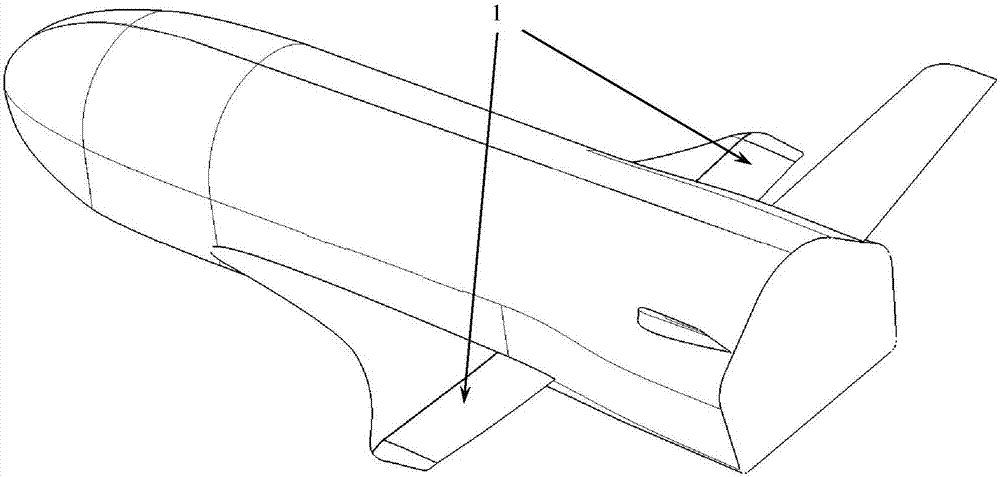
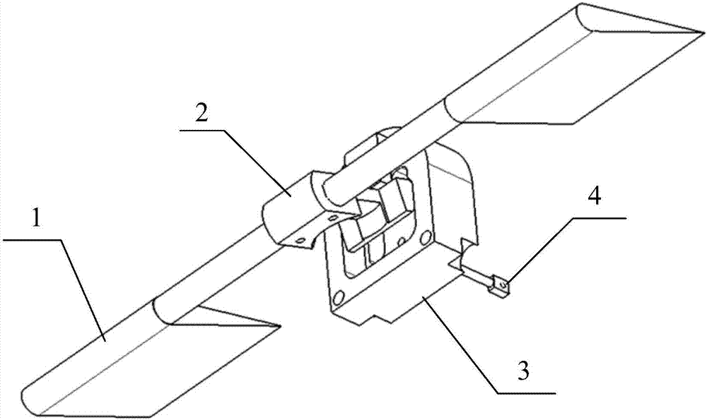
[0030] Such as figure 1 Shown is a schematic diagram of the position of the rudder surface in the free-flying model of the present invention, and the rudder surface assembly 1 is located at the rear section of the airfoils on both sides of the free-flying model. Such as figure 2 Shown is the structure diagram of the rudder surface deflection device of the present invention, the rudder surface deflection device of the present invention comprises a rudder surface assembly 1, a rotating shaft block 2, a compression spring 5, a pull pin 4, a rudder deflection control block 3 and a base plate 6 ( figure 2 Compression spring 5 and bottom plate 6 are not shown in ).

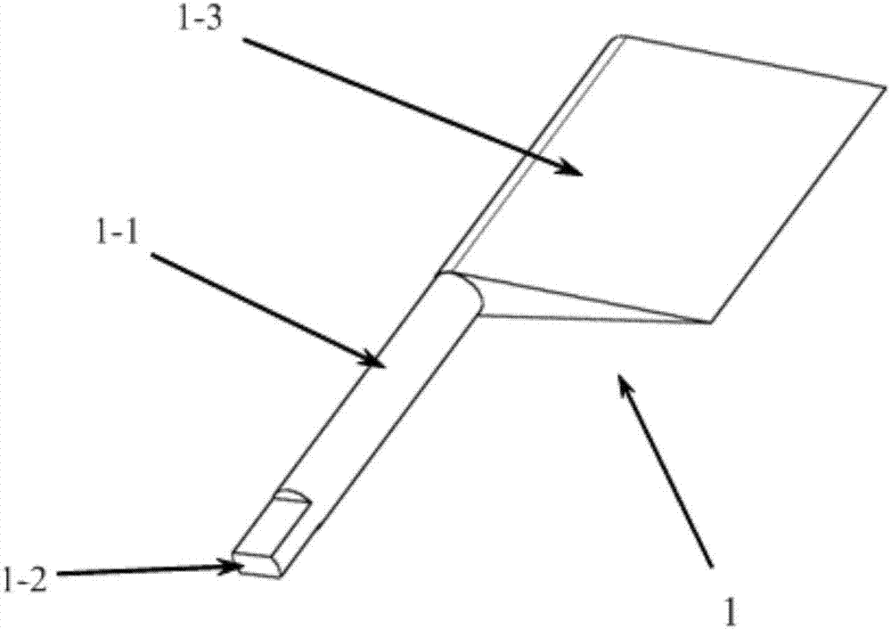
[0031] Such as image 3 Shown is the structure diagram of the rudder surface assembly of the present invention, and there are two rudder surface assemblies 1. It can be seen from the...


PUM


Abstract

The invention relates to a control plane deflection apparatus of a free-flight model. The control plane deflection apparatus comprises control plane assemblies, a rotating shaft block, a compression spring, and a rudder deflection control block. A left control plane and a right control plane are connected to a mounting hole of the same rotating shaft block by respective rudder shafts and bosses arranged at the tails of the rudder shafts and are screwed into circular holes of the rotating shaft block by bolts to fix the control planes and the rotating shaft block so as to prevent shedding of the control planes. The control plane assemblies and the rotating shaft block can rotate around the axes of the rudder shafts. A rotating shaft block angle control plane is arranged at the rotating shaft block; and a rotating shaft block blind hole is formed in the rotating shaft block. The compression spring is arranged in the rotating shaft block blind hole; and one end of the compression spring is abutted against the bottom of the rotating shaft block blind hole and the other end is fixed. A rudder deflection control plane is arranged at the rudder deflection control block; and the control plane deflection angle of the control plane can be adjusted by adjusting the height of the rudder deflection control plane. According to the invention, problems of small size of the wind tunnel free-flight model model and large difficulty of mechanism designing as well as a problem of difficult control plane deflectin triggering and angle controlling of the model during the wind tunnel free-flight support-free process can be solved.

Description

technical field [0001] The invention relates to mechanical design and wind tunnel tests, in particular to a free-flying model rudder surface deflection device, which belongs to the fields of mechanical design and aerospace engineering. Background technique [0002] The rudder surface is the main control surface of the aircraft. In order to obtain sufficient maneuverability, most aircraft rely on the deflection of the rudder surface to provide a variety of control torques. However, as the flight speed increases, the aerodynamic efficiency of the rudder deflection will decrease significantly, which directly threatens the flight stability of the aircraft. and mobility. [0003] A variety of existing hypersonic vehicles still use rudder surfaces to provide control torque. Aiming at the problem of rudder surface efficiency of hypersonic vehicles, the main experimental research method at present is to use static techniques such as static force measurement. Although this kind of t...

Claims


Application Information

Patent Timeline
IPC IPC(8): G01M9/08
CPCG01M9/08
Inventor 薛飞朱剑杨益农王誉超
Owner CHINA ACAD OF AEROSPACE AERODYNAMICS
Why Eureka
Try Eureka