Substrate with pixel structure, optoelectronic device containing same and printing method

A pixel structure and substrate technology, applied in the direction of electric solid devices, electrical components, semiconductor devices, etc., can solve the problem of uneven film layer, and achieve the effect of improving the uniformity of the film layer

Active Publication Date: 2020-09-08
NANJING TECH CORP LTD
View PDF4 Cites 0 Cited by
  • Summary
  • Abstract
  • Description
  • Claims
  • Application Information

AI Technical Summary

Problems solved by technology

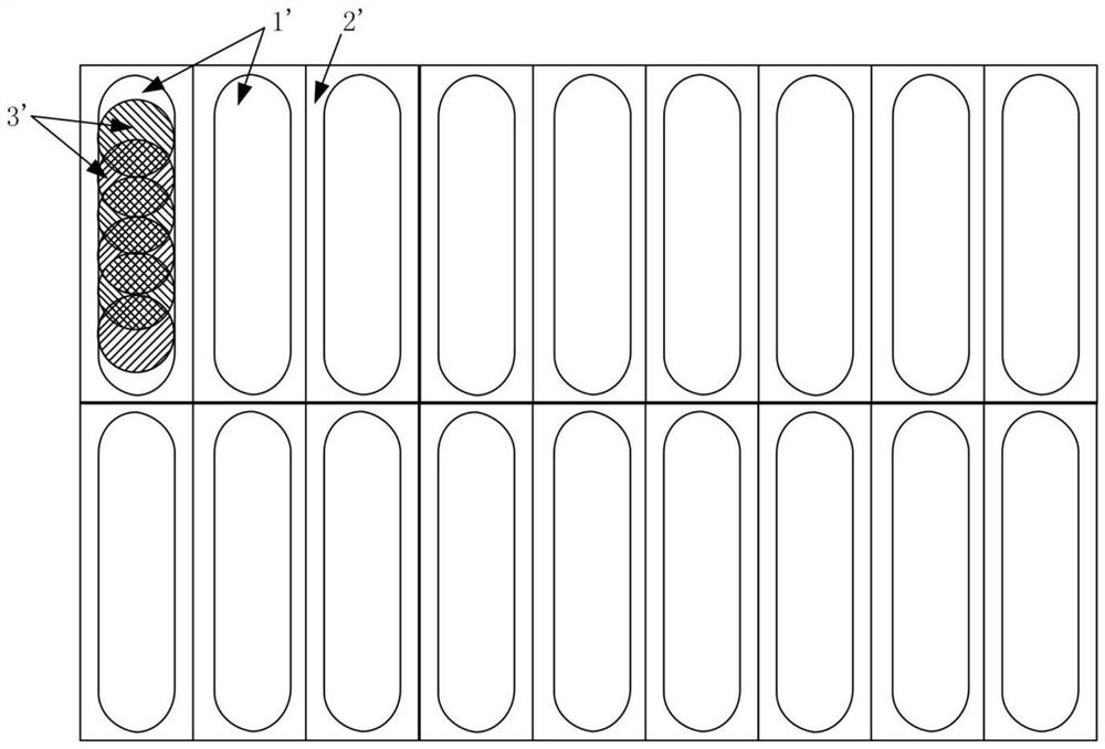
[0006] The main purpose of this application is to provide a substrate with a pixel structure, an optoelectronic device containing it, and a printing method to solve the problem that the light-emitting device prepared by the existing inkjet printing method is prone to uneven film layers

Method used


Image

  • Substrate with pixel structure, optoelectronic device containing same and printing method
  • Substrate with pixel structure, optoelectronic device containing same and printing method
  • Substrate with pixel structure, optoelectronic device containing same and printing method

Examples


Embodiment Construction

[0027] It should be noted that, in the case of no conflict, the embodiments in the present application and the features in the embodiments can be combined with each other. The present application will be described in detail below with reference to the accompanying drawings and embodiments.

[0028] In order to enable those skilled in the art to better understand the solution of the present application, the technical solution in the embodiment of the application will be clearly and completely described below in conjunction with the accompanying drawings in the embodiment of the application. Obviously, the described embodiment is only It is an embodiment of a part of the application, but not all of the embodiments. Based on the embodiments in this application, all other embodiments obtained by persons of ordinary skill in the art without creative efforts shall fall within the scope of protection of this application.

[0029] It should be noted that the terms "first" and "second...


PUM

PropertyMeasurementUnit
heightaaaaaaaaaa

Abstract

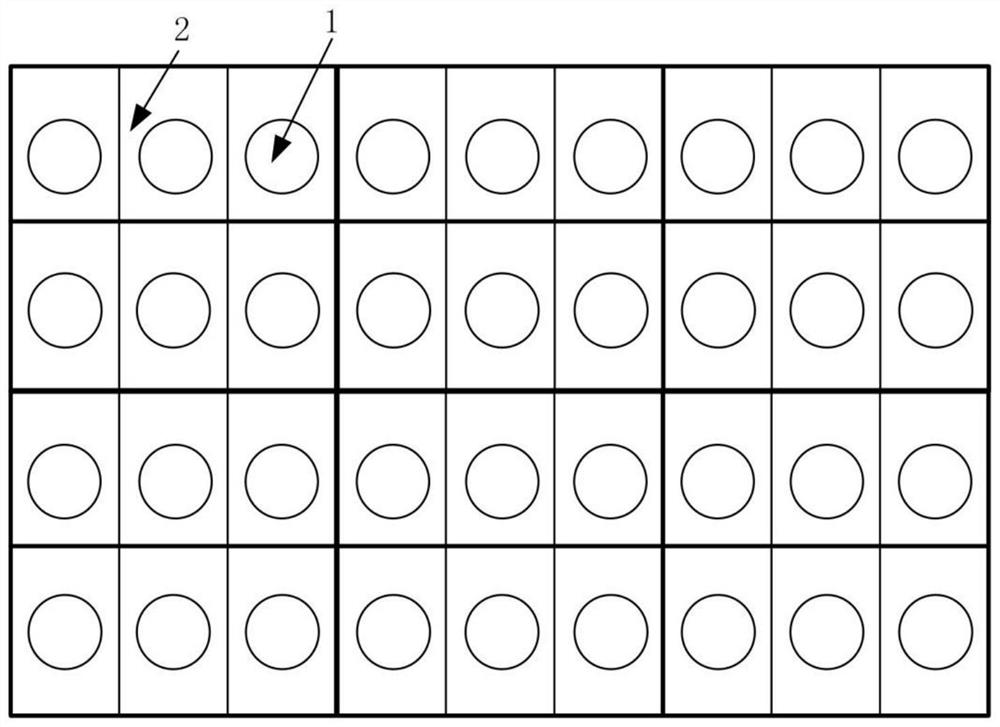
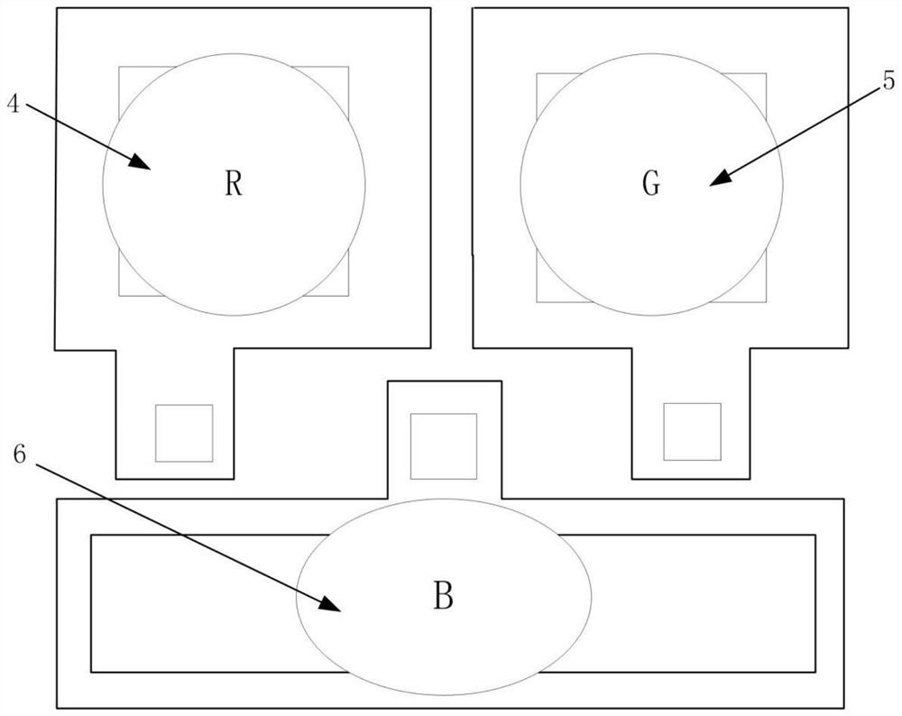
The application provides a substrate with a pixel structure, an optoelectronic device containing the same and a printing method. The pixel structure in the substrate with the pixel structure includes a pixel unit with sub-pixels, each sub-pixel includes a pixel isolation area and a light-emitting area, the light-emitting area is the area where the pixel isolation structure in the pixel isolation area and the depression surrounded by the substrate are located, and the depression It is used to contain the liquid material ejected by the inkjet printing device. The shape of the bottom surface of the depression is the first plane figure S1, the area of ​​1≤S2 / the area of ​​S1≤1.5, and S2 and S1 have an intersection, the intersection is S1, and S2 is The inkjet printing device prints the ejected liquid material once at a specific height from the test substrate, and forms a second plane figure after drying on the flat surface of the test substrate. The test substrate is a conductive substrate without a pixel isolation layer structure . The present application achieves the effect of improving the uniformity of the film layer in the light-emitting region and the uniformity of light emission of the light-emitting device.

Description

technical field [0001] The present application relates to the technical field of pixel design, in particular, to a substrate with a pixel structure, an optoelectronic device containing it, and a printing method. Background technique [0002] In recent years, the solution method has gradually replaced the traditional evaporation method and has become a research hotspot in the manufacture of electroluminescent devices. The process of manufacturing electroluminescent devices mainly includes setting corresponding functional inks into corresponding pixels. Generally, pixels include pixel defining layers and The light-emitting area, the light-emitting area is a pit surrounded by the pixel defining layer and the substrate. The pit is used to hold ink. After the ink is dried, each film layer (each functional layer and light-emitting layer) is formed. Each film layer and the upper and lower electrodes form a light-emitting area. device. [0003] Among the solution methods, inkjet pr...

Claims


Application Information

Patent Timeline
Patent Type & Authority Patents(China)
IPC IPC(8): H01L27/32H01L51/56
CPCH10K59/122H10K59/17H10K71/135H10K71/00
Inventor 彭军军
Owner NANJING TECH CORP LTD
Why Eureka
Try Eureka