
Riveting jig

A riveting and jig technology, which is applied to manufacturing tools, metal processing equipment, feeding devices, etc., can solve the problems of inconvenient riveting, small size of conductive pins, and affecting processing efficiency.

Active Publication Date: 2017-10-10
GUANGDONG EVERWIN PRECISION TECH
View PDF7 Cites 3 Cited by
  • Summary
  • Abstract
  • Description
  • Claims
  • Application Information

AI Technical Summary

Problems solved by technology

As a kind of manufacturing process in the mobile phone industry, mobile phone case processing also needs continuous improvement. The existing mobile phone case processing and manufacturing generally adopts hardware profile CNC (Computer numerical control, CNC for short) processing and molding, and conductive pins need to be riveted during the processing process. Press it to a specific position on the phone case, but the size of the conductive pin is small, which is inconvenient for riveting and will affect the processing efficiency

Method used


Image

  • Riveting jig
  • Riveting jig
  • Riveting jig

Examples


Embodiment Construction

[0018] In order to facilitate the understanding of the present invention, the present invention will be described more fully below with reference to the associated drawings. Preferred embodiments of the invention are shown in the accompanying drawings. However, the present invention can be embodied in many different forms and is not limited to the embodiments described herein. On the contrary, these embodiments are provided to make the understanding of the disclosure of the present invention more thorough and comprehensive.

[0019] It should be noted that when an element is referred to as being “fixed” to another element, it can be directly on the other element or there can also be an intervening element. When an element is referred to as being "connected to" another element, it can be directly connected to the other element or intervening elements may also be present. The terms "vertical," "horizontal," "left," "right," and similar expressions are used herein for purposes ...


PUM


Abstract

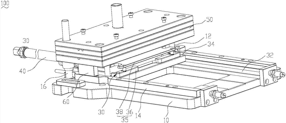
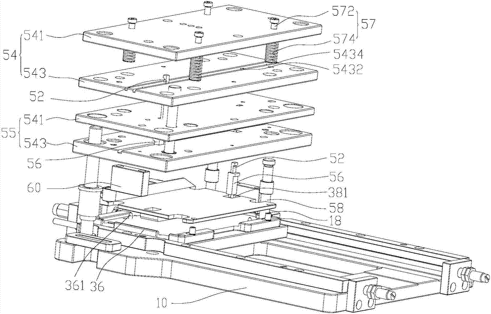
The invention relates to a riveting jig. The riveting jig comprises a base, a carrying mechanism and a riveting mechanism, wherein the carrying mechanism is movably arranged on the base; the riveting mechanism is arranged on the base, the riveting mechanism and the base are arranged at an interval, and an accommodating space for accommodating the carrying mechanism is formed in the interval; the carrying mechanism comprises a spreading position and a riveting position in a moving process; the carrying mechanism is used for carrying workpieces when in the spreading position; the carrying mechanism moves to the accommodating space when in the riveting position, and the riveting mechanism can be operated to rise and descend relative to the carrying mechanism to rivet the workpieces. The carrying mechanism of the riveting jig drives a placed mobile phone shell and electric conductive pin to move to the riveting position in the accommodating space, then the riveting mechanism descends in a direction close to the carrying mechanism and rivets the electric conductive pin on the mobile phone shell, pressing of the electric conductive pin is completed, and accordingly, riveting processing of the electric conductive pin on the mobile phone shell is completed conveniently and efficiently through the jig of the mobile phone shell and the electric conductive pin.

Description

technical field [0001] The invention relates to the field of jigs for processing mobile phone shells, in particular to a riveting jig. Background technique [0002] With the advent of the information age, the existing communication equipment is constantly developing, and mobile phones, as a kind of communication equipment, are also constantly developing. Nowadays, mobile phones are being updated faster and faster, and the manufacturing process of the mobile phone industry also needs to continue to move forward. develop. As a kind of manufacturing process in the mobile phone industry, mobile phone case processing also needs continuous improvement. The existing mobile phone case processing and manufacturing generally adopts hardware profile CNC (Computer numerical control, CNC for short) processing and molding, and conductive pins need to be riveted during the processing process. Press it to a specific position on the phone case, but the size of the conductive pin is small, w...

Claims


Application Information

Patent Timeline
IPC IPC(8): B21D39/00B21D43/02
CPCB21D39/00B21D43/02
Inventor 欧阳梅生
Owner GUANGDONG EVERWIN PRECISION TECH
Learn More