A tool damage detection method based on visual inspection of CNC machine tools

A visual inspection, CNC machine tool technology, applied in the direction of manufacturing tools, measuring/indicating equipment, metal processing machinery parts, etc., can solve problems such as inconvenience in production, increase overall cost, occupy space, etc., and achieve the effect of tool breakage detection

Active Publication Date: 2020-03-31
沈阳机床(东莞)智能装备有限公司
View PDF7 Cites 0 Cited by
  • Summary
  • Abstract
  • Description
  • Claims
  • Application Information

AI Technical Summary

Problems solved by technology

[0006] In view of the deficiencies of the above-mentioned prior art, the object of the present invention is to provide a tool damage detection method based on the visual inspection of CNC machine tools, aiming at solving the need to rely on additional visual inspection equipment for the detection of tool wear of CNC machine tools in the prior art, Increase the overall cost, take up more space, and cause inconvenience to production

Method used


Image

  • A tool damage detection method based on visual inspection of CNC machine tools
  • A tool damage detection method based on visual inspection of CNC machine tools
  • A tool damage detection method based on visual inspection of CNC machine tools

Examples


Embodiment Construction

[0033] The present invention provides a tool breakage detection method based on the visual detection of CNC machine tools. In order to make the purpose, technical solution and effect of the present invention clearer and clearer, the present invention will be further described in detail below with reference to the accompanying drawings and examples. It should be understood that the specific embodiments described here are only used to explain the present invention, not to limit the present invention.

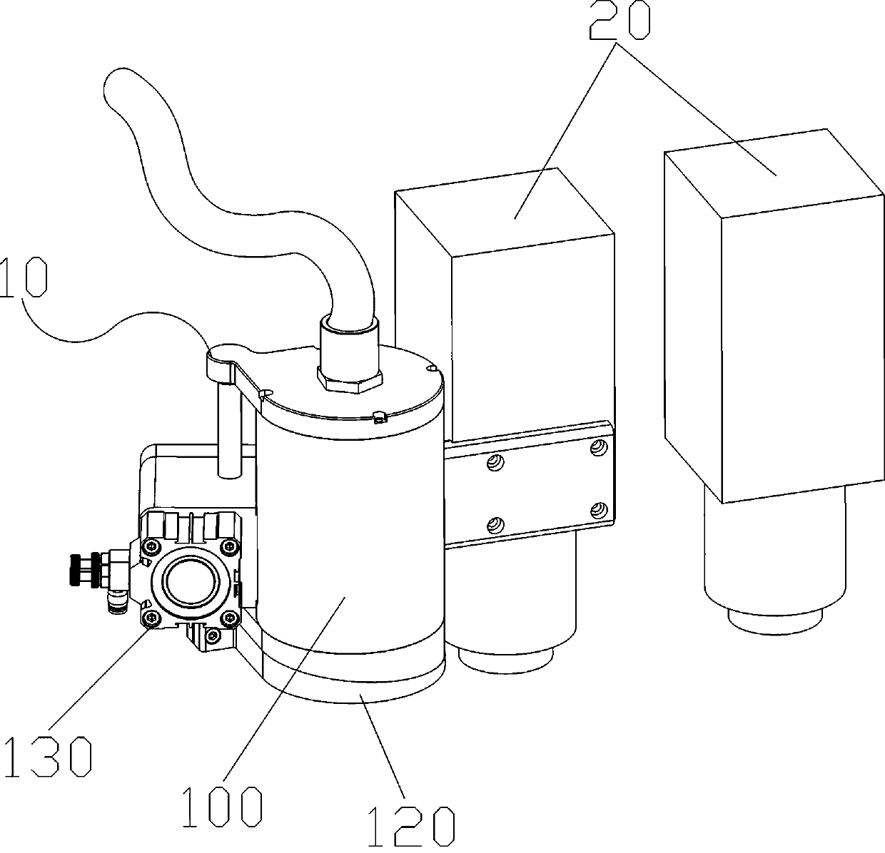
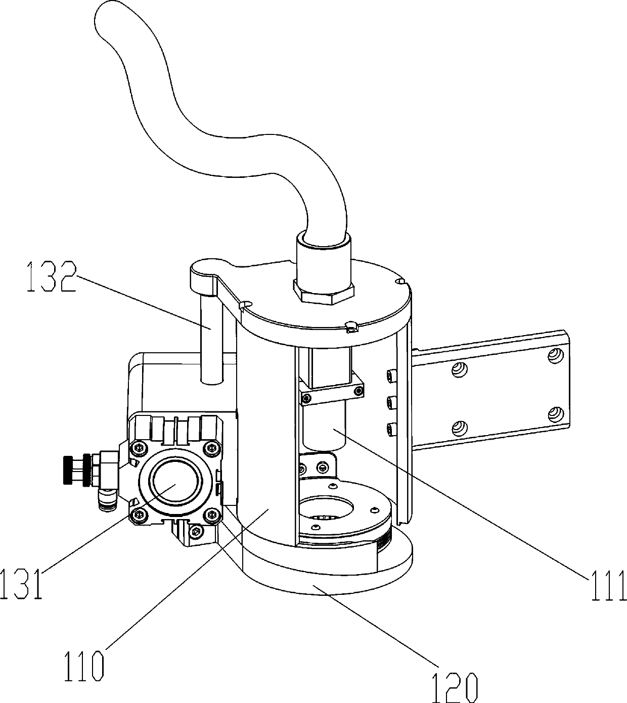
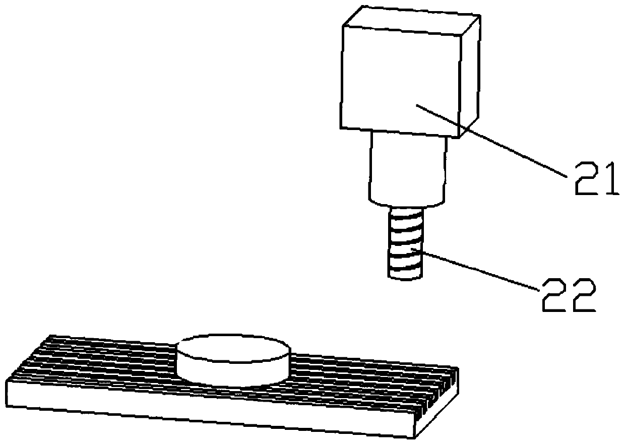
[0034] Please also refer to Figure 1 to Figure 3 , figure 1 It is a perspective view of a tool breakage detection system based on the visual detection of a numerically controlled machine tool in the present invention. figure 2 It is a three-dimensional view of the optical positioning mechanism of the tool breakage detection system based on the visual detection of the numerical control machine tool in the present invention. image 3 It is a schematic diagram of the working stat...


PUM


Abstract

The invention provides a cutter damage degree detection method based on numerically controlled machine tool visual inspection. The cutter damage degree detection method comprises the following steps of: step A. obtaining the image of a processed part; step B. carrying out filtering noise-elimination treatment on the image, and then carrying out grey level transformation to obtain a pretreated image; step C. finding and locating in the pretreated image according to preset characteristic information to complete the cutting remainder of the processed part, thereby obtaining a part picture; step D. carrying out edge detection on cut marks, and drawing an edge contour line; step E. calculating the size of the edge width of a cutter according to the edge contour line; and step F. comparing the practical width of the cutter with a preset theoretical standard value, and then outputting a detection result. The cutter damage degree detection method has the beneficial effects that only original optical locating equipment in a numerically controlled machine tool is needed, and the indirect detection of the cutter damage degree can be realized by using the method provided by the invention after the processed part is shot; additional optical detection equipment does not need to be installed; and the cutter damage degree detection can be realized by implementing the method on the basis of existing equipment.

Description

technical field [0001] The invention relates to the field of detection methods for numerically controlled machine tools, in particular to a method for detecting tool breakage based on visual detection of numerically controlled machine tools. Background technique [0002] CNC machine tool is an automatic machine tool equipped with a program control system. After the numerical control device is processed, various control signals are sent by the numerical control device to control the movement of the machine tool, and the parts are automatically processed according to the shape and size required by the drawing. . During the above-mentioned processing, the tool installed in the CNC machine tool needs to cut the part according to the preset program. Since the tool itself will be damaged during the cutting process, it is necessary to monitor the damage degree of the tool. To ensure For the accuracy of parts cutting, when the damage of the tool exceeds a certain level, the tool ne...

Claims


Application Information

Patent Timeline
Patent Type & Authority Patents(China)
IPC IPC(8): B23Q17/24B23Q17/20
CPCB23Q17/2471
Inventor 赵星王大鹏杨勇张彦龙朱峰李钊成景凤伟陈诗赠鲁卓王龙吴云峰
Owner 沈阳机床(东莞)智能装备有限公司
Why Eureka
Try Eureka