Ceiling board damping structure

A technology for ceiling boards and connection structures, applied in the direction of ceilings, building components, building structures, etc., can solve problems affecting the integrity and stability of the ceiling system, weakening of the section of the connection position, and the falling structure of the mineral wool board, so as to improve the overall Performance and shock absorption performance, convenient construction, good overall effect

Inactive Publication Date: 2017-10-10
BEIJING NEW BUILDING MATERIALS PLC
View PDF0 Cites 3 Cited by
  • Summary
  • Abstract
  • Description
  • Claims
  • Application Information

AI Technical Summary

Problems solved by technology

[0002] First of all, in the construction of the suspended ceiling, the main joist and the sub joist often need to be connected at the junction of the main joist and the sub joist. When the main keel is handed over, the connection at the handover position is realized by plugging the end connectors. The problem with this connection method is that at the handover position of the main keel and the secondary keel, the connection is only made on the contact surface of the main keel and the secondary keel, and due to The connecting piece is set on the keel body, which itself will weaken the section at the connecting position, so when the suspended ceiling is subjected to vibration (vibration), this position is prone to mineral wool board falling off or structural deformation due to vibration (vibration)
[0003] Secondly, in the construction of the suspended ceiling, due to the limitation of the size of the keel, it is often necessary to lengthen the keel in the extension direction. The existing way of lengthening the keel is to use the pre-set connectors at the ends of the keel. The problem of this connection method is that the connection part of the keel extension belongs to the plane connection. When the ceiling is subjected to vibration (vibration), this position is easy to fall off or deform due to vibration (vibration)
[0004] Thirdly, in the ceiling system, the connection between the side keel and the frame keel, the existing connection method is that the frame keel is directly built on the bottom plate of the side keel, and generally no connection measures are taken. Or impact, the skeleton keel is easy to shift, thus affecting the integrity and stability of the entire ceiling system
[0005] Finally, in the existing ceiling system, the ceiling board is directly placed on the bottom plate of the keel, and there is no connection with the bottom board, and there is no other limit measure, which means it is in a free state. When the ceiling board is pushed upward by the bottom (such as a large wind or shock (vibration) movement), the ceiling board may be lifted or even fall off. In order to avoid the above problems during use, it is an engineering problem that must be solved to find a way to fix the ceiling board during the ceiling installation process.

Method used


Image

  • Ceiling board damping structure
  • Ceiling board damping structure
  • Ceiling board damping structure

Examples


Embodiment Construction

[0075] In order to make the purpose of the invention, technical solutions and beneficial effects of the present invention clearer, the embodiments of the present invention will be described below in conjunction with the accompanying drawings. The features in can be combined arbitrarily with each other.

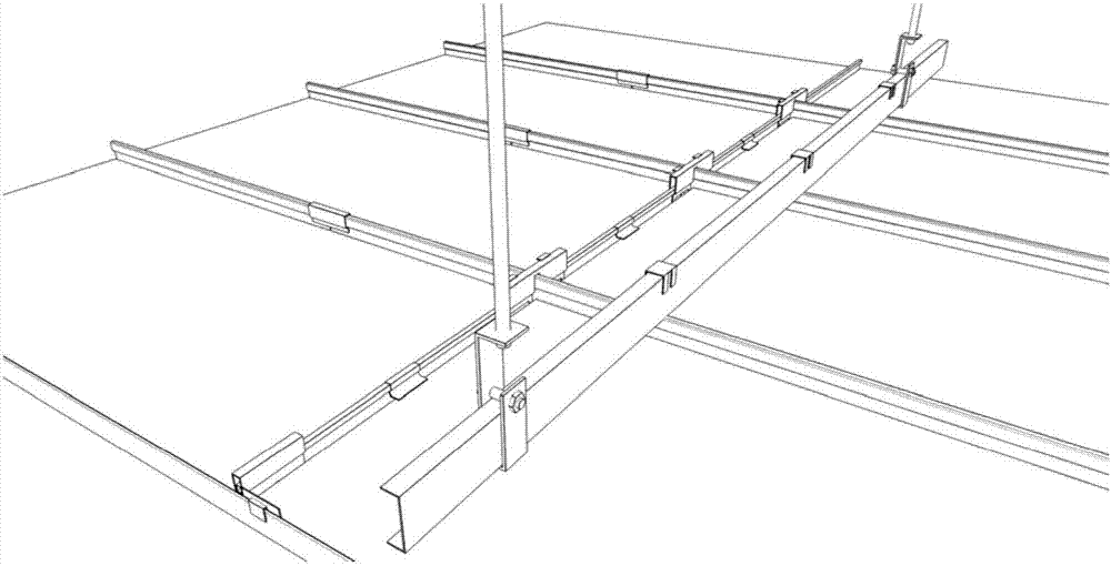
[0076] See figure 1 , figure 1 It is a schematic diagram of the shock-absorbing structure of the ceiling plate, including the main keel, the secondary keel, the side keel and the ceiling slab. The main keel and the secondary keel constitute the skeleton keel. The ceiling plate is set on the skeleton keel, and the skeleton keel is set on the side keel. The connection structure with the secondary keel, the combined keel extension node between the main keel or the secondary keel, the connection structure between the side keel and the skeleton keel, and the positioning structure of the ceiling board.

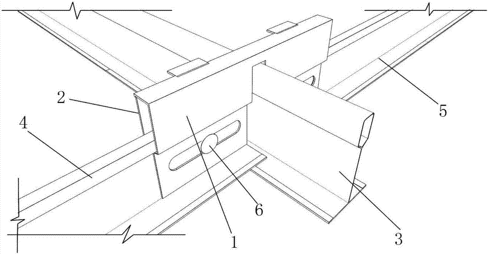
[0077] See figure 2 , figure 2 Schematic diagram of the connection struct...


PUM


Abstract

The application relates to a shock-absorbing structure of a suspended ceiling plate, which includes a main keel, a secondary keel, a side keel and a suspended ceiling plate. It is characterized in that it also includes the connecting structure of the main keel and the secondary keel, the combined keel extension node between the main keel or the secondary keel, the connecting structure of the side keel and the skeleton keel, and the positioning structure of the ceiling board. The application solves the problem of connection reliability among the main keel, the secondary keel, the side keel and the ceiling board, and is especially suitable for a ceiling system with high requirements for shock absorption (vibration).

Description

technical field [0001] The present application relates to the technical field of building decoration engineering, in particular to a shock-absorbing structure of a ceiling plate in building decoration engineering. Background technique [0002] First of all, in the construction of the suspended ceiling, the main joist and the sub joist often need to be connected at the junction of the main joist and the sub joist. When the main keel is handed over, the connection at the handover position is realized by plugging the end connectors. The problem with this connection method is that at the handover position of the main keel and the secondary keel, the connection is only made on the contact surface of the main keel and the secondary keel, and due to The connecting piece is arranged on the keel body, which itself will weaken the section at the connecting position, so when the ceiling is subjected to vibration (vibration), the position is prone to mineral wool board falling off or st...

Claims


Application Information

Patent Timeline
Patent Type & Authority Applications(China)
IPC IPC(8): E04B9/12
CPCE04B9/125
Inventor 赵云平李昂管理
Owner BEIJING NEW BUILDING MATERIALS PLC
Why Eureka
Try Eureka