Injection molded part and method of making the same

a technology of injection molding and parts, which is applied in the direction of washers, ways, bolts, etc., can solve the problems that the connection of threaded fasteners exclusively using die plastics cannot meet the strength requirements, injection molded parts cannot be lighter configuration, and the strength requirements cannot be maintained any longer, so as to achieve the effect of producing with a lower weight and the same strength

Active Publication Date: 2013-05-30
CONTITECH VIBRATION CONTROL
View PDF12 Cites 2 Cited by
  • Summary
  • Abstract
  • Description
  • Claims
  • Application Information

AI Technical Summary

Benefits of technology

[0005]It is an object, of the invention to provide an injection molded part which is suitable for mass manufacture and can be produced with a lower weight and an identical strength. It is also an object of the invention to provide a method which is suitable for this purpose and a suitable injection molding machine.

Problems solved by technology

The threaded fastener connection with the insert part which is made from metal is sufficiently stable, whereas a threaded fastener connection exclusively with die plastic does not meet the strength requirements as a rule.
Up to now, however, injection molded parts have not been able to be of lighter configuration in the region of the insert part, since otherwise the strength requirements cannot be maintained any longer.
Although it would be possible to use higher strength plastics or to modify the construction of the injection molded part in the region around the insert part, this has not been possible up to now on account of the associated higher manufacturing cost.
The higher the tolerance requirements, the more expensive the manufacture of the insert part.

Method used


Image

  • Injection molded part and method of making the same
  • Injection molded part and method of making the same
  • Injection molded part and method of making the same

Examples


Embodiment Construction

[0048]First, a method will be described for making an injection molded part according to the invention.

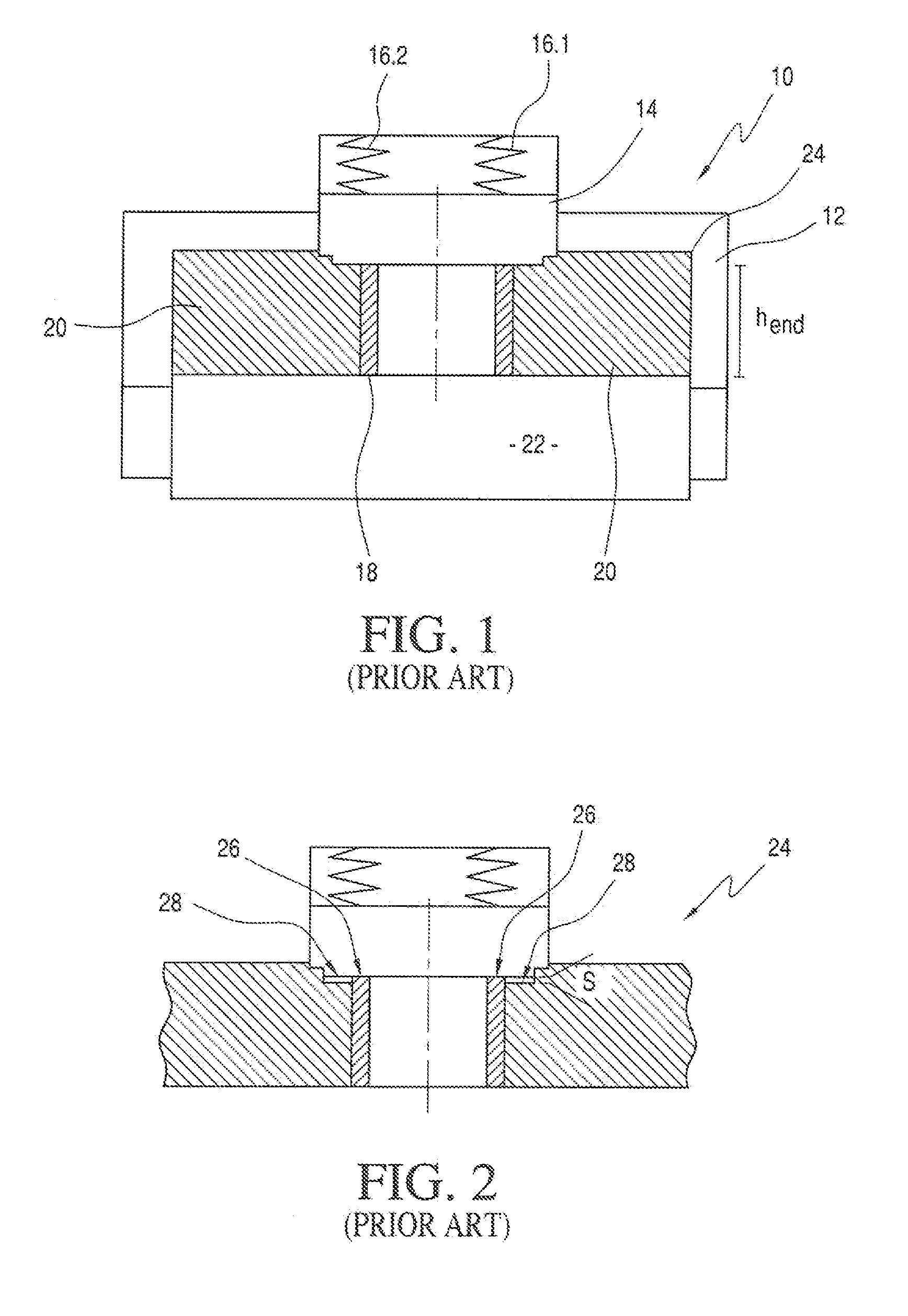
[0049]FIG. 1 shows an injection mold 10 according to the prior art which is of a three-piece construction, and a first basic part 13, to which a mold insert 14 is held by springs (16.1, 16.2). An insert part 18 is arranged in the injection mold 10, which Insert part 18 is embedded in plastic 20.

[0050]The known injection mold 10 is used in the context of an injection molding method, in which first the insert part. 18 is inserted into the injection mold 10. A second basic part 22 is then pushed into the first basic part 12 by a predefined amount. When the insert part 18 has a height (h) which does not correspond exactly to the nominal height but rather is greater, the second basic part 22 pushes the insert part 18 against the mold insert 14, whereupon the springs 16 yield. Subsequently, the plastic 20 is injected around the insert part 18, with the result that an injection molded par...


PUM

PropertyMeasurementUnit
pressureaaaaaaaaaa
recessed distanceaaaaaaaaaa
stress forceaaaaaaaaaa

Abstract

An injection molded part accommodates a threaded fastener and includes a metal insert. The insert defines a longitudinal axis and has an end face and an outer peripheral surface. A cutout extends from the end face and through the insert to permit the threaded fastener to extend therethrough. A plastic body surrounds the outer peripheral surface and has a threaded fastener contact face. The threaded fastener contact face of the plastic, body is recessed at a recessed distance below the end face of the insert which has a spring constant with respect to the longitudinal axis. The recessed distance and the spring constant are selected to deform the insert in response to a stress force applied to the end face thereof by the threaded fastener to cause a pregiven component of the stress force to be introduced into the threaded fastener contact face of the plastic body.

Description

CROSS REFERENCE TO RELATED APPLICATIONS[0001]This application is a continuation application of international patent application PCT / EP2011 / 058323, filed May 23, 2011, designating the United States and claiming priority from German application 10 2010 036 596.3, filed Jul. 23, 2010, and the entire content of both applications is incorporated herein by reference.FIELD OF THE INVENTION[0002]The invention relates to an injection molded part having (a) a sleeve-shaped insert part which is made from metal and has a longitudinal axis, an end face, a recess which runs through the end face, reaches through the insert part, and is configured for plugging through a threaded fastener, and an outer peripheral surface, and (b) a plastic body which surrounds the outer peripheral surface and has a threaded fastener contact face which extends along a contact plane which runs perpendicularly with respect to the longitudinal axis and with regard to a height, along the longitudinal axis in the region o...

Claims


Application Information

Patent Timeline
Patent Type & Authority Applications(United States)
IPC IPC(8): F16B43/00B29C45/14
CPCB29C45/1418B29C45/1459B29K2705/00F16B43/00F16B19/02B29C45/14778F16B5/02
Inventor SCHNEIDER, DIETHARDLINGNER, THOMASBRODERSEN, JANEBERHARD, GUENTERWICHMANN, MARC
Owner CONTITECH VIBRATION CONTROL
Why Eureka
Try Eureka